Figure 9. mic input mix w/common mode rejection, Figure 10. differential input, As illustrated in – Cirrus Logic CS42L51 User Manual
Page 30: Figure 9, Illustrated in, Figure 10, Cs42l51
30
DS679F1
CS42L51
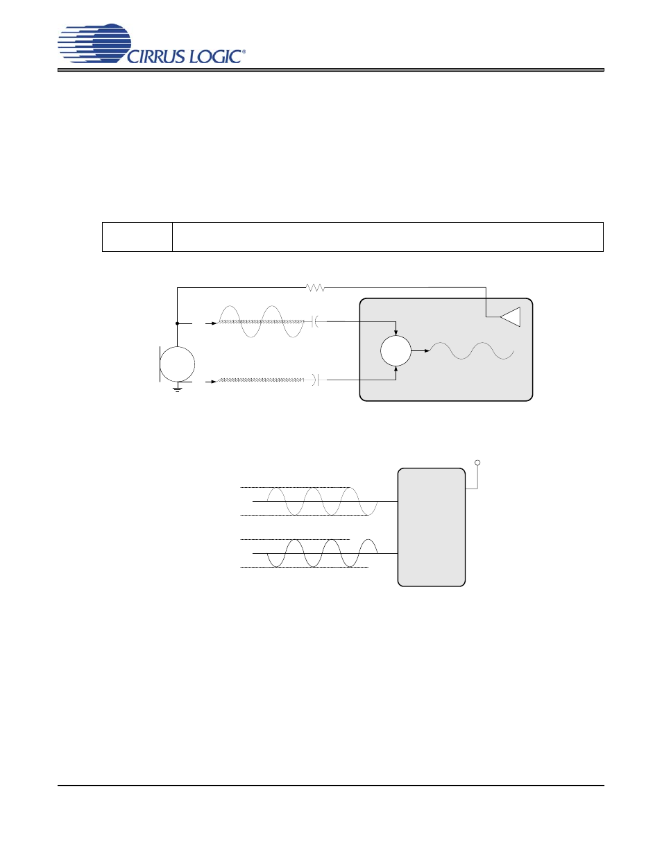
The MICBIAS series resistor must be selected based on the requirements of the particular microphone
used. The MICBIAS output pin is selected using the MICBIAS_SEL bit.
Software
Controls:
“Interface Control (Address 04h)” on page 52
“MIC Control (Address 05h)” on page 53
.
fc
1
2
π 50 kΩ
(
) 1 µF
(
)
-----------------------------------------------
3.18 Hz
=
=
MICIN1
MICIN2
Σ
+
+
MICBIAS
18
17
20
//
//
Figure 9. MIC Input Mix w/Common Mode Rejection
Full-Scale Differential Input Level (MICMIX=1)
= (AINxA - AINxB) = 3.6 V
PP
= 1.27 V
RMS
AINxA
AINxB
2.15 V
1.25 V
0.35 V
2.5 V
2.15 V
1.25 V
0.35 V
VA
Figure 10. Differential Input
See also other documents in the category Cirrus Logic Hardware:
- CobraNet (147 pages)
- CS4961xx (54 pages)
- CS150x (8 pages)
- CS1501 (16 pages)
- CS1601 (2 pages)
- CS1601 (16 pages)
- CS1610 (16 pages)
- CRD1610-8W (24 pages)
- CRD1611-8W (25 pages)
- CDB1610-8W (21 pages)
- CS1610A (18 pages)
- CDB1611-8W (21 pages)
- CDB1610A-8W (21 pages)
- CDB1611A-8W (21 pages)
- CRD1610A-8W (24 pages)
- CRD1611A-8W (25 pages)
- CS1615 (16 pages)
- AN403 (15 pages)
- AN401 (14 pages)
- AN400 (15 pages)
- AN375 (27 pages)
- AN376 (9 pages)
- CRD1615-8W (22 pages)
- CRD1616-8W (23 pages)
- AN402 (14 pages)
- AN404 (15 pages)
- CRD1615A-8W (21 pages)
- CS1615A (16 pages)
- CS1630 (56 pages)
- AN374 (35 pages)
- AN368 (80 pages)
- CRD1630-10W (24 pages)
- CRD1631-10W (25 pages)
- CS1680 (16 pages)
- AN405 (13 pages)
- AN379 (31 pages)
- CRD1680-7W (31 pages)
- AN335 (10 pages)
- AN334 (6 pages)
- AN312 (14 pages)
- AN Integrating CobraNet into Audio Products (16 pages)
- CobraNet Audio Routing Primer (9 pages)
- Bundle Assignments in CobraNet Systems (3 pages)
- CS2300-01 (3 pages)
- CS2000-CP (38 pages)