7 automatic level control (alc), Figure 11. alc, Figure 11.alc – Cirrus Logic CS42L51 User Manual
Page 32: Cs42l51
32
DS679F1
CS42L51
4.3.7
Automatic Level Control (ALC)
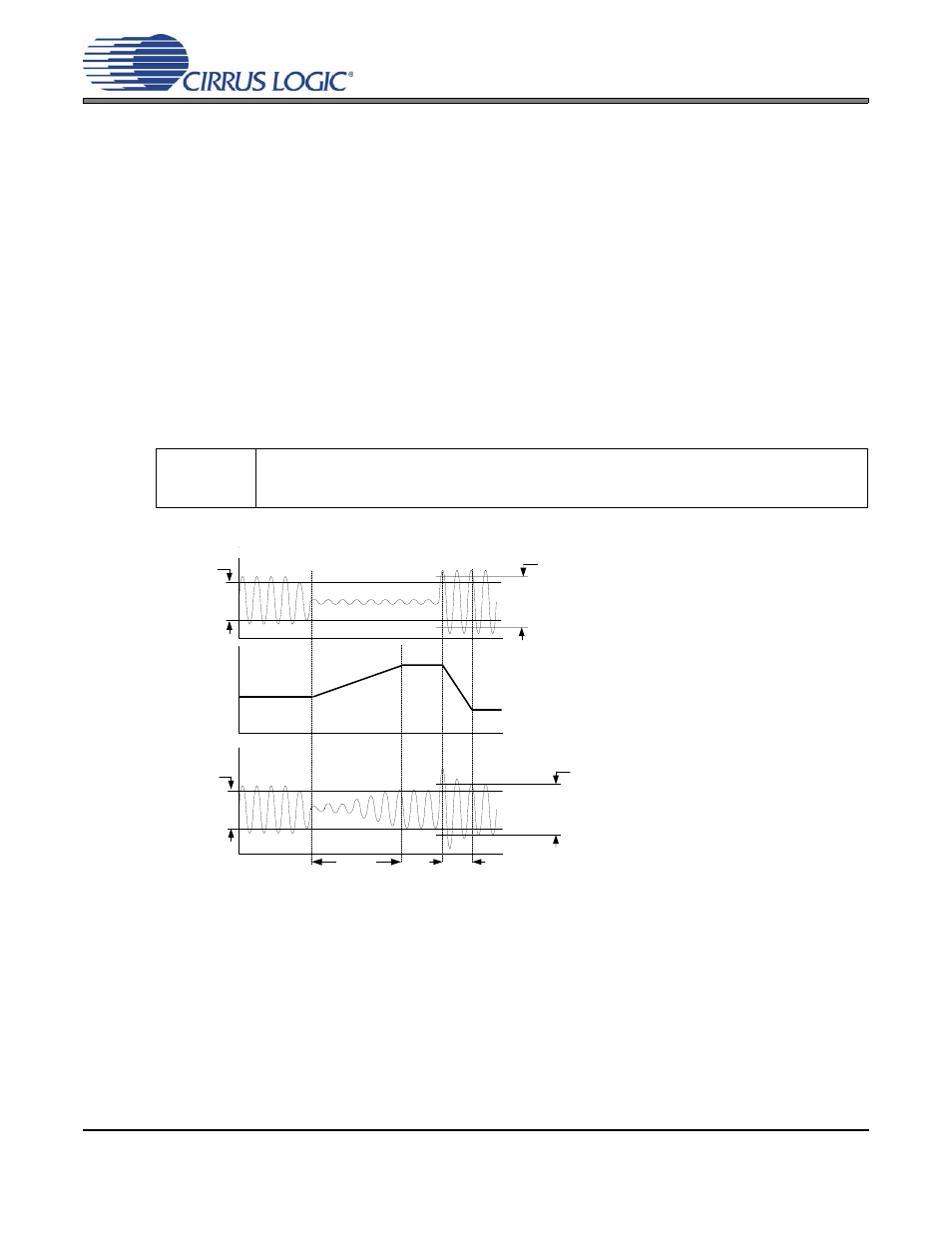
When enabled, the ALC monitors the analog input signal after the digital attenuator, detects when peak
levels exceed the maximum threshold settings and lowers, first, the PGA gain settings and then increases
the digital attenuation levels at a programmable attack rate and maintains the resulting level below the
maximum threshold.
When input signal levels fall below the minimum threshold, digital attenuation levels are decreased first
and the PGA gain is then increased at a programmable release rate and maintains the resulting level
above the minimum threshold.
Attack and release rates are affected by the ADC soft ramp/zero cross settings and sample rate, Fs. ALC
soft ramp and zero cross dependency may be independently enabled/disabled.
Recommended settings: Best level control may be realized with the fastest attack and slowest release
setting with soft ramp enabled in the control registers.
Note: 1.) The maximum realized gain must be set
in the PGAx_VOL register. The ALC will only apply the gain set in the PGAx_VOL.
2.) The ALC maintains
the output signal between the MIN and MAX thresholds. As the input signal level changes, the level-con-
trolled output may not always be the same but will always fall within the thresholds.
Software
Controls:
“ALC Enable & Attack Rate (Address 1Ch)” on page 70
“ALC Release Rate (Address 1Dh)” on
“ALC Threshold (Address 1Eh)” on page 71
“ALCX & PGAX Control: ALCA, PGAA
(Address 0Ah) & ALCB, PGAB (Address 0Bh)” on page 59
Output
(after ALC)
Input
RRATE[5:0]
PGA Gain and/or
Attenuator
ALC
MAX[2:0]
ARATE[5:0]
below full scale
MIN[2:0]
below full scale
MIN[2:0]
below full scale
MAX[2:0]
below full scale
ADCx_ATT[7:0] and
PGAx_VOL[4:0] volume
controls should NOT be
adjusted manually when
ALCx is enabled.
Figure 11. ALC