Making adjustments to your saw, Adjusting y our saw – SawStop 3.0HP User Manual
Page 85
SawStop 10” Professional Cabinet Saw 83
Adjusting Y
our
Saw
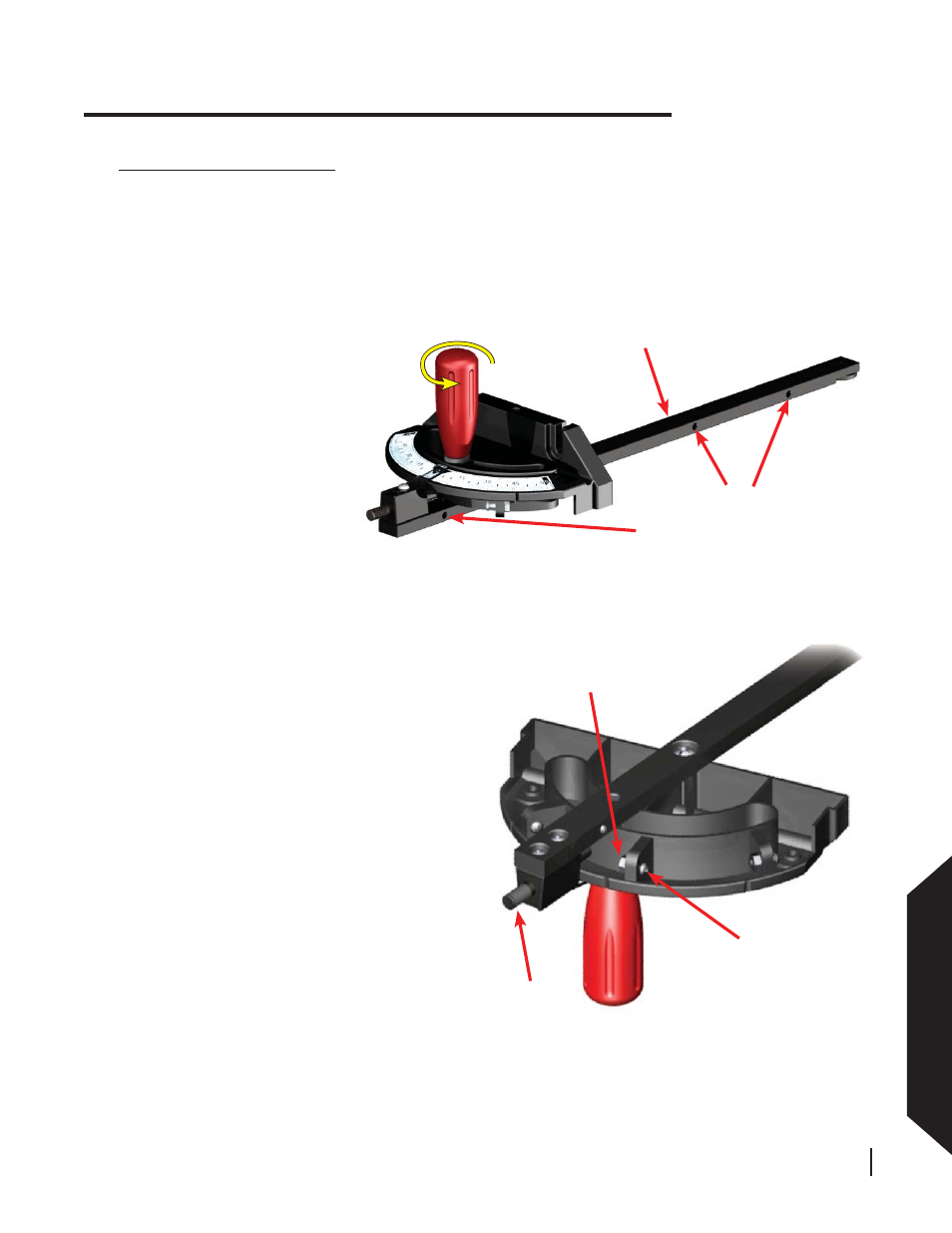
locking nut
set screw
indexing
pin
Fig. 133
Fig. 132
turn locking
handle to unlock
miter gauge head
main bar
insert hex wrench to
adjust spring bearing
Fig. 132
Making Adjustments to Your Saw
Next, for the indexing stop you want to adjust,
loosen the corresponding locking nut on the
bottom of the miter gauge head and turn the set
screw counter-clockwise several turns (see
Fig. 133). Place the miter gauge in either the left
or right miter slot, and set a combination square
to the desired angle (e.g., -45°, 0°, or +45°).
Position one leg of the square flush against the
blade and rotate the miter gauge head until it is
flush against the other leg of the square.
Next, turn the handle clockwise until tight to
lock the miter gauge head at the correct angle.
Make sure the indexing pin is pressed in toward
the miter gauge bar, then turn the set screw
clockwise until it hits against the indexing pin.
Finally, tighten the locking nut to prevent the set
screw from moving.
Repeat the above process for the other indexing
stops if desired.
Adjusting the Miter Gauge
The miter gauge bar includes three spring bearings which ensure a close fi t between the miter gauge main bar
and the miter gauge slots in the table. The bearings can be adjusted to protrude further outward from the side
of the main bar to tighten the fi t between the main bar and the miter slots. Alternatively, the bearings can be
adjusted inward to loosen the fi t. To adjust the position of the spring bearings, insert a 2.5 mm hex wrench into
the back of the bearing as shown in Fig. 132. Turn the wrench clockwise to tighten the fi t, or counter-clockwise
to loosen the fi t.
The miter gauge also includes
indexing stops to allow you to
quickly set the gauge to -45°,
0°, and +45°. If necessary, you
can adjust these indexing stops
to increase the precision of your
miter cuts.
To begin, loosen the miter gauge
head by turning the locking
handle counter-clockwise about
1
⁄
2
turn (see Fig. 132).