2 unboxing the chassis, 2 unboxing the chassis -2 – Allied Telesis 9700 iMAP User Manual
Page 8
Unboxing the chassis
ATI 9700 Configuration
ATI 9700 - Installation Guide (Initial Installation of the ATI 9700)
1-2
Note:
When the power supply is 60V, the shelf will support only 48V/60V cards, and not 48V cards.
For information on the SMs, CMs. and NMs supported on the 9700 with a 60V power supply
refer to the ATI Component Specification.
1.2 Unboxing the chassis
To unbox the chassis:
1.
Cut and remove the outer plastic wrap.
2.
Cut and remove the plastic retainer straps.
3.
Remove the top box and place to the side.
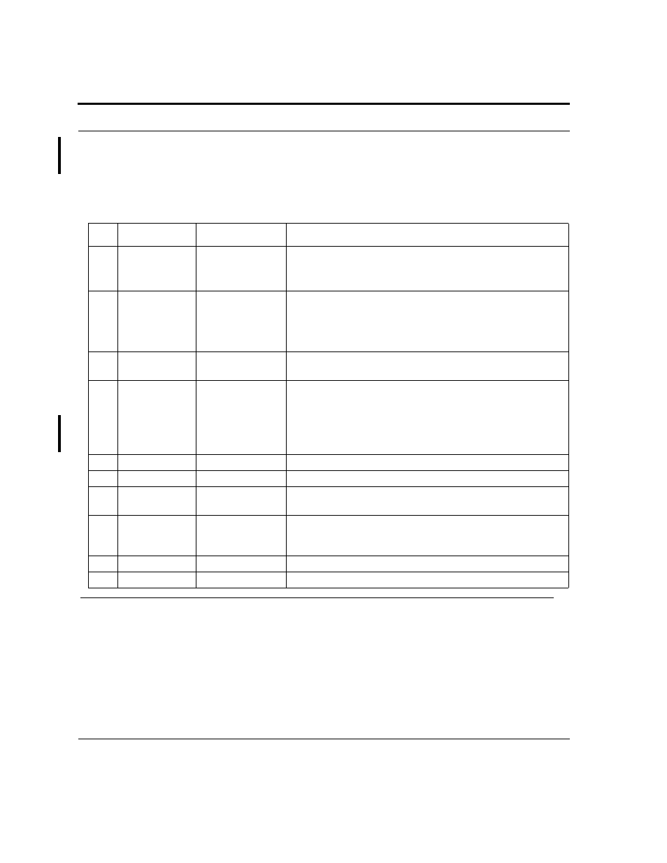
TABLE 1-1
Listing of components with slot/position and configuration notes
No.
Module
Slot/Position
Configuration Notes
A
Service Module
(SM)
0-7 (left), 14-21
(right), and either 8
or 12.
At least one can be configured. Unused slots must be configured
with Filler Plate Fulls (FPF). A mixture of SMs can be configured.
At least one SM must be configured in order to provide service.
B
Control Module
(CM)
8, 9 (double) and
12,13 (Duplex
mode)
At least one card per shelf (occupies two slots).
Duplex mode - Control Module in slots 8/9 and 12/13
Simplex mode - Control Module in slots 8/9 or 12/13. A Service
Module can be inserted into slots 8 or 12 if in Simplex Mode.
C
Network Mod-
ule (NM)
Slot 10 and Slot 11
At least one is always configured. An unused half-slot requires a
Filler Plate Half (FPH).
D
PEM8
Bottom of chassis
Power Entry Module. Includes power feeds, signal ground, returns,
and A/B circuit breakers.
Note:
The PEM8 that supports a 48V/60V power
supply (E002-C) must be used for a 60V power
supply
E
FAN8
Top of chassis
Fan Module
F
ESD
Left side
ESD wrist strap connection point.
NA
FPF
Full-height panel
for Service Module
Required when SM slot is not used. Ensures proper airflow and EMI
compliance.
NA
FPH
Half-height panel
for Network Mod-
ule
Required when half-slot for NM is not used. Ensures proper airflow
and EMI compliance.
G
Ground
Right side
Primary ground connection
H
Air Filter
Bottom of chassis
Air filter