24 ati contact information, 24 ati contact information -44, Rt. see – Allied Telesis 9700 iMAP User Manual
Page 49
Check management interfaces
ATI Contact Information
1-43
ATI 9700 - Installation Guide (Initial Installation of the ATI 9700)
2.
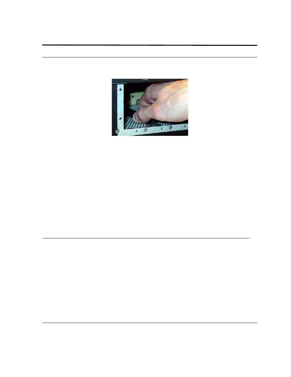
Remove the bottom guide rail. (Note that it is easier to remove the bottom rail by loosening the retaining
guide bracket.) Refer to the following figure.
FIGURE 1-29
Removing Bottom Guide Rail
12.
If installed in slot 10, remove the GE3 card.
13.
Insert the new PEM8 (TN-E002-C). Since guide rails are not used, guide the Power Supply into the PEM8
slot until the PEM8 is seated properly and the retaining screw holes line up.
14.
Install the seven retaining screws into the new PEM8.
15.
Reconnect the A and B power cables to the PEM8.
16.
Reinsert the GE3 into slot 10 if it was removed.
17.
Reinstall the guard shields.
18.
Turn the Power Supply breakers to the ON position. (The breakers are horizontal in the E002-C PEM8.)
19.
Restart the power supply to the shelf, following local practice. (Examples would be inserting power supply
fuses or setting circuit breakers back to ON.
20.
Using a voltmeter, ensure there is the proper voltage between the 48V and RTN leads. (Refer to
.)
21.
Redress the power cables.
22.
Ensure the shelf powers up correctly. Refer to
.
1.24 ATI Contact Information
If assistance or information is required in the installation of this equipment, contact ATI Technical Support or
your ATI Representative.