Dc o ut faul t, System poe+ / system poe+ / system system, Dc ou t fault – Allied Telesis AT-RPS3000 User Manual
Page 81
AT-RPS3000 Redundant Power Supply Installation Guide
81
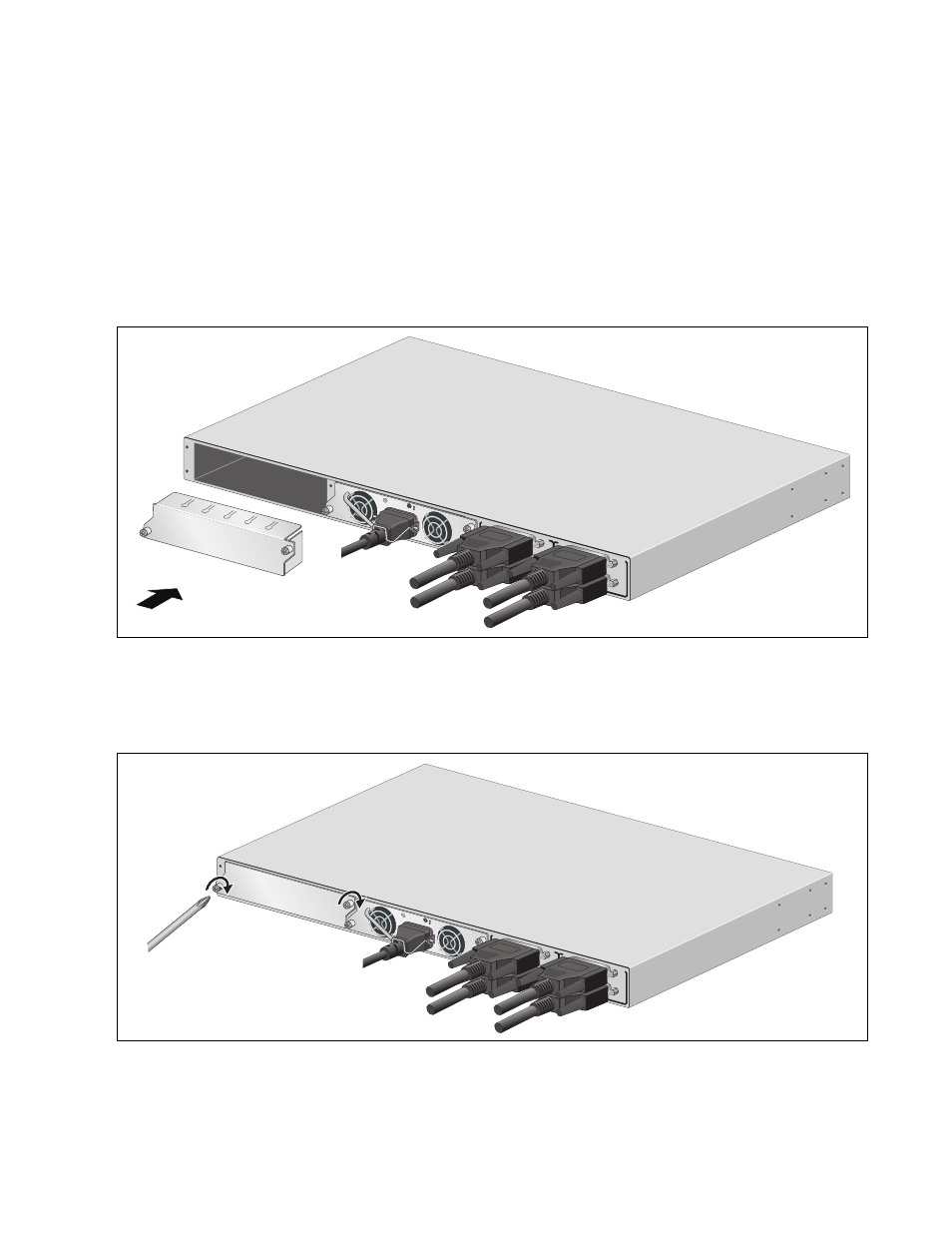
6. If you are not replacing the module, cover the empty slot with one of
the slot covers, labeled AT-PNL250 and AT-PNL800/1200, provided
with the unit.
The faceplates of the power supply modules and the slot covers are
keyed so that the slot cover has to correspond to the power supply
module you installed in the unit. Use the AT-PNL250 Blank Panel if the
chassis contains the AT-PWR250 Power Supply Module, or the
AT-PNL800/1200 Blank Panel if it has the AT-PWR800 or
AT-PWR1200 Power Supply Module.
Figure 62. Installing the Slot Cover
7. Secure the slot cover to the chassis by tightening the two captive
screws.
Figure 63. Securing the Slot Cover
B
B
1
2
3
4
SYSTE
M
PoE+ /
SYST
EM
PoE+ /
SYST
EM
SYSTE
M
MODULE
B
MODULE
A
A
A
A
T
-PWR
8
00
DC O
UT
FAUL
T
AT-PNL800/
1200
2173
100-240 V
AC~12A
MAX
B
B
1
2
3
4
SYSTEM
PoE+ /
SYSTEM
PoE+ /
SYSTEM
SYSTEM
MODULE B
MODULE A
A
A
AT-PN
L800/1
200
A
T
-PWR
8
00
DC OU
T
FAULT
2174
100-24
0 VAC~
12A M
AX
- AT-GS908M (54 pages)
- AT-x230-10GP (80 pages)
- AT-GS950/48PS (64 pages)
- AT-GS950/10PS (386 pages)
- AT-GS950/16PS (386 pages)
- AT-GS950/48PS (386 pages)
- AT-9000 Series (1480 pages)
- AT-9000 Series (258 pages)
- IE200 Series (70 pages)
- AT-GS950/48 (410 pages)
- AT-GS950/8 (52 pages)
- AT-GS950/48 (378 pages)
- AT-GS950/48 (60 pages)
- SwitchBlade x8106 (322 pages)
- SwitchBlade x8112 (322 pages)
- SwitchBlade x8106 (240 pages)
- SwitchBlade x8112 (240 pages)
- AT-TQ Series (172 pages)
- AlliedWare Plus Operating System Version 5.4.4C (x310-26FT,x310-26FP,x310-50FT,x310-50FP) (2220 pages)
- FS970M Series (106 pages)
- 8100L Series (116 pages)
- 8100S Series (140 pages)
- x310 Series (120 pages)
- x310 Series (116 pages)
- AT-GS950/24 (404 pages)
- AT-GS950/24 (366 pages)
- AT-GS950/16 (44 pages)
- AT-GS950/16 (404 pages)
- AT-GS950/16 (364 pages)
- AT-GS950/8 (404 pages)
- AT-GS950/8 (364 pages)
- AT-GS950/8 (52 pages)
- AT-8100 Series (330 pages)
- AT-8100 Series (1962 pages)
- AT-FS970M Series (330 pages)
- AT-FS970M Series (1938 pages)
- SwitchBlade x3106 (288 pages)
- SwitchBlade x3112 (294 pages)
- SwitchBlade x3106 (260 pages)
- SwitchBlade x3112 (222 pages)
- AT-S95 CLI (AT-8000GS Series) (397 pages)
- AT-S94 CLI (AT-8000S Series) (402 pages)
- AT-IMC1000T/SFP (23 pages)
- AT-IMC1000TP/SFP (24 pages)
- AT-SBx3106WMB (44 pages)