Power supply modules, Table 10: power supply module components – Allied Telesis AT-RPS3000 User Manual
Page 55
AT-RPS3000 Redundant Power Supply Installation Guide
55
Note
The AT-RPS3000 Chassis is connected to an x610 Series switch
with the AT-RPS-CBL1.0 cable. The cable must be purchased
separately. You will need one cable for each x610 Series switch.
Power Supply
Modules
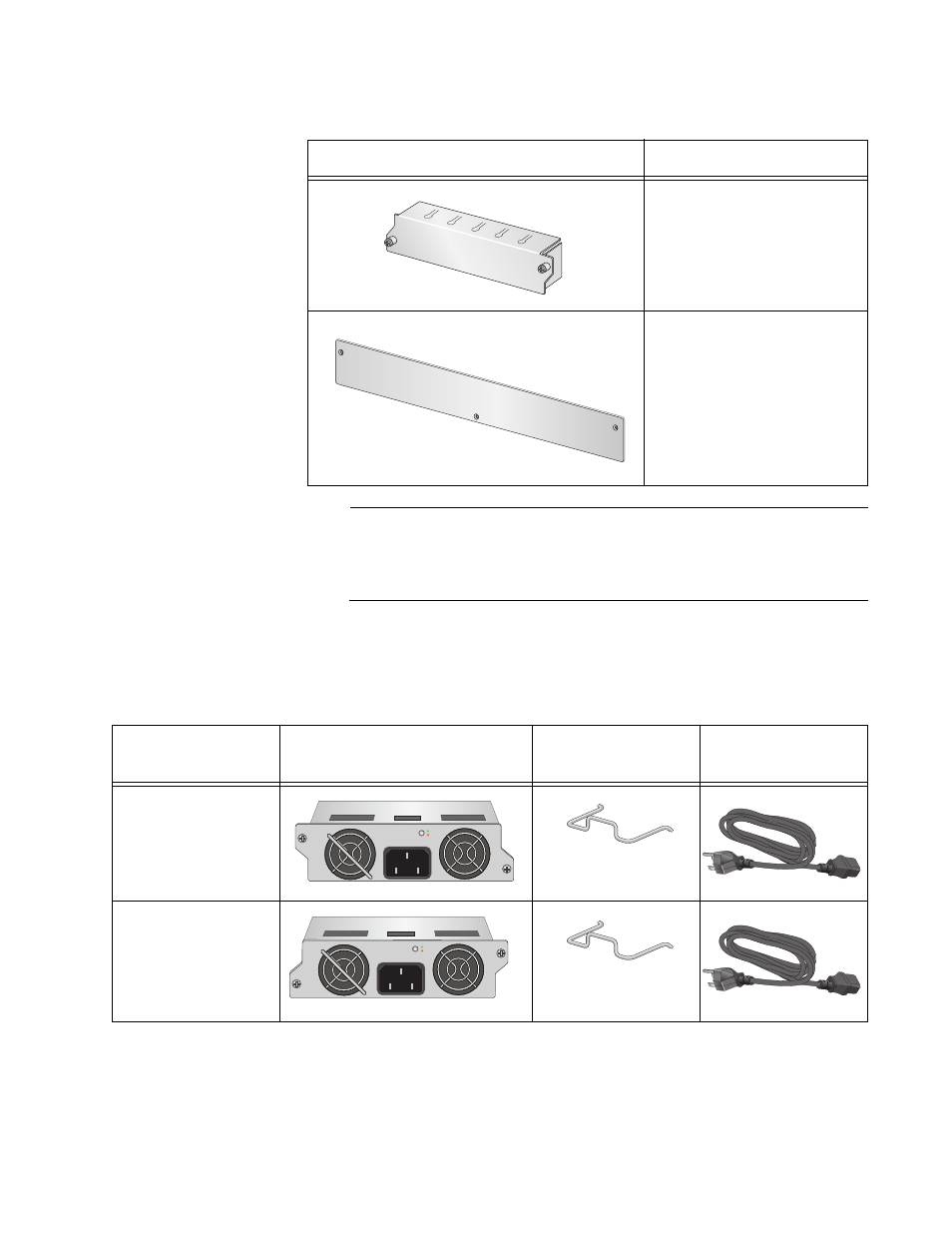
Refer to this table to verify the items in the shipping containers of the
power supply modules.
One AT-PNL800/1200
Blank Panel
Blank shipping panel (pre-
installed on the power
supply slots on the back
panel)
Table 9. AT-RPS3000 Chassis Components
Component
Description
AT-PNL800/
1200
2160
2189
Table 10. Power Supply Module Components
Power Supply
Module
Module
Power Cord
Retaining Clip
Regional Power
Cord
AT-PWR250
AT-PWR800
2185
A
T
-PWR250
100-240VAC~ 5A MAX
DC OUT
FAULT
2184
157
2186
A
T
-PWR800
100-240VAC~ 12A MAX
DC OUT
FAULT
2184
157
- AT-GS908M (54 pages)
- AT-x230-10GP (80 pages)
- AT-GS950/48PS (64 pages)
- AT-GS950/10PS (386 pages)
- AT-GS950/16PS (386 pages)
- AT-GS950/48PS (386 pages)
- AT-9000 Series (258 pages)
- AT-9000 Series (1480 pages)
- IE200 Series (70 pages)
- AT-GS950/48 (378 pages)
- AT-GS950/48 (60 pages)
- AT-GS950/48 (410 pages)
- AT-GS950/8 (52 pages)
- SwitchBlade x8106 (322 pages)
- SwitchBlade x8112 (322 pages)
- SwitchBlade x8106 (240 pages)
- SwitchBlade x8112 (240 pages)
- AT-TQ Series (172 pages)
- AlliedWare Plus Operating System Version 5.4.4C (x310-26FT,x310-26FP,x310-50FT,x310-50FP) (2220 pages)
- FS970M Series (106 pages)
- 8100S Series (140 pages)
- 8100L Series (116 pages)
- x310 Series (116 pages)
- x310 Series (120 pages)
- AT-GS950/16 (44 pages)
- AT-GS950/24 (404 pages)
- AT-GS950/24 (366 pages)
- AT-GS950/16 (404 pages)
- AT-GS950/16 (364 pages)
- AT-GS950/8 (404 pages)
- AT-GS950/8 (364 pages)
- AT-GS950/8 (52 pages)
- AT-8100 Series (330 pages)
- AT-8100 Series (1962 pages)
- AT-FS970M Series (330 pages)
- AT-FS970M Series (1938 pages)
- SwitchBlade x3106 (288 pages)
- SwitchBlade x3112 (294 pages)
- SwitchBlade x3106 (260 pages)
- SwitchBlade x3112 (222 pages)
- AT-S95 CLI (AT-8000GS Series) (397 pages)
- AT-S94 CLI (AT-8000S Series) (402 pages)
- AT-IMC1000T/SFP (23 pages)
- AT-IMC1000TP/SFP (24 pages)
- AT-SBx3106WMB (44 pages)