Dc o ut faul t – Allied Telesis AT-RPS3000 User Manual
Page 63
AT-RPS3000 Redundant Power Supply Installation Guide
63
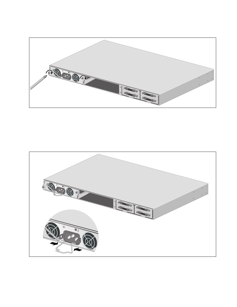
3. Secure the module to the chassis by tightening the two captive screws.
Figure 41. Securing a Power Supply Module
4. For the AT-PWR250 or AT-PWR800 Module, install the power cord
retaining clip on the AC power socket by pressing the sides of the clip
inward and inserting the two ends into the holes on the power socket.
(The AT-PWR1200 Module does not come with a power cord retaining
clip.)
Figure 42. Installing a Power Cord Retaining Clip
5. To install a second power supply module, repeat steps 2 through 4.
B
B
1
2
3
4
SYSTEM
PoE+ /
SYSTEM
PoE+ /
SYSTEM
SYSTEM
MODULE B
MODULE A
A
A
AT
-P
W
R
8
00
DC O
UT
FAUL
T
2176
100-240
VAC~12A
MAX
B
B
1
2
3
4
SYSTE
M
PoE+ /
SYST
EM
PoE+ /
SYST
EM
SYSTE
M
MODULE
B
MODULE
A
A
A
A
T
-PWR
8
00
DC O
UT
FAUL
T
DC O
UT
FAU
LT
2153
100-24
0 VAC~
12A M
AX
100-240
VAC~12
A MAX
- AT-GS908M (54 pages)
- AT-x230-10GP (80 pages)
- AT-GS950/48PS (64 pages)
- AT-GS950/10PS (386 pages)
- AT-GS950/16PS (386 pages)
- AT-GS950/48PS (386 pages)
- AT-9000 Series (258 pages)
- AT-9000 Series (1480 pages)
- IE200 Series (70 pages)
- AT-GS950/48 (378 pages)
- AT-GS950/48 (60 pages)
- AT-GS950/48 (410 pages)
- AT-GS950/8 (52 pages)
- SwitchBlade x8106 (322 pages)
- SwitchBlade x8112 (322 pages)
- SwitchBlade x8106 (240 pages)
- SwitchBlade x8112 (240 pages)
- AT-TQ Series (172 pages)
- AlliedWare Plus Operating System Version 5.4.4C (x310-26FT,x310-26FP,x310-50FT,x310-50FP) (2220 pages)
- FS970M Series (106 pages)
- 8100L Series (116 pages)
- 8100S Series (140 pages)
- x310 Series (116 pages)
- x310 Series (120 pages)
- AT-GS950/24 (404 pages)
- AT-GS950/24 (366 pages)
- AT-GS950/16 (44 pages)
- AT-GS950/16 (404 pages)
- AT-GS950/16 (364 pages)
- AT-GS950/8 (364 pages)
- AT-GS950/8 (52 pages)
- AT-GS950/8 (404 pages)
- AT-8100 Series (330 pages)
- AT-8100 Series (1962 pages)
- AT-FS970M Series (330 pages)
- AT-FS970M Series (1938 pages)
- SwitchBlade x3106 (288 pages)
- SwitchBlade x3112 (294 pages)
- SwitchBlade x3106 (260 pages)
- SwitchBlade x3112 (222 pages)
- AT-S95 CLI (AT-8000GS Series) (397 pages)
- AT-S94 CLI (AT-8000S Series) (402 pages)
- AT-IMC1000T/SFP (23 pages)
- AT-IMC1000TP/SFP (24 pages)
- AT-SBx3106WMB (44 pages)