Figure 19: example of an invalid configuration - b, Figure 19. example of an invalid configuration - b – Allied Telesis AT-RPS3000 User Manual
Page 35
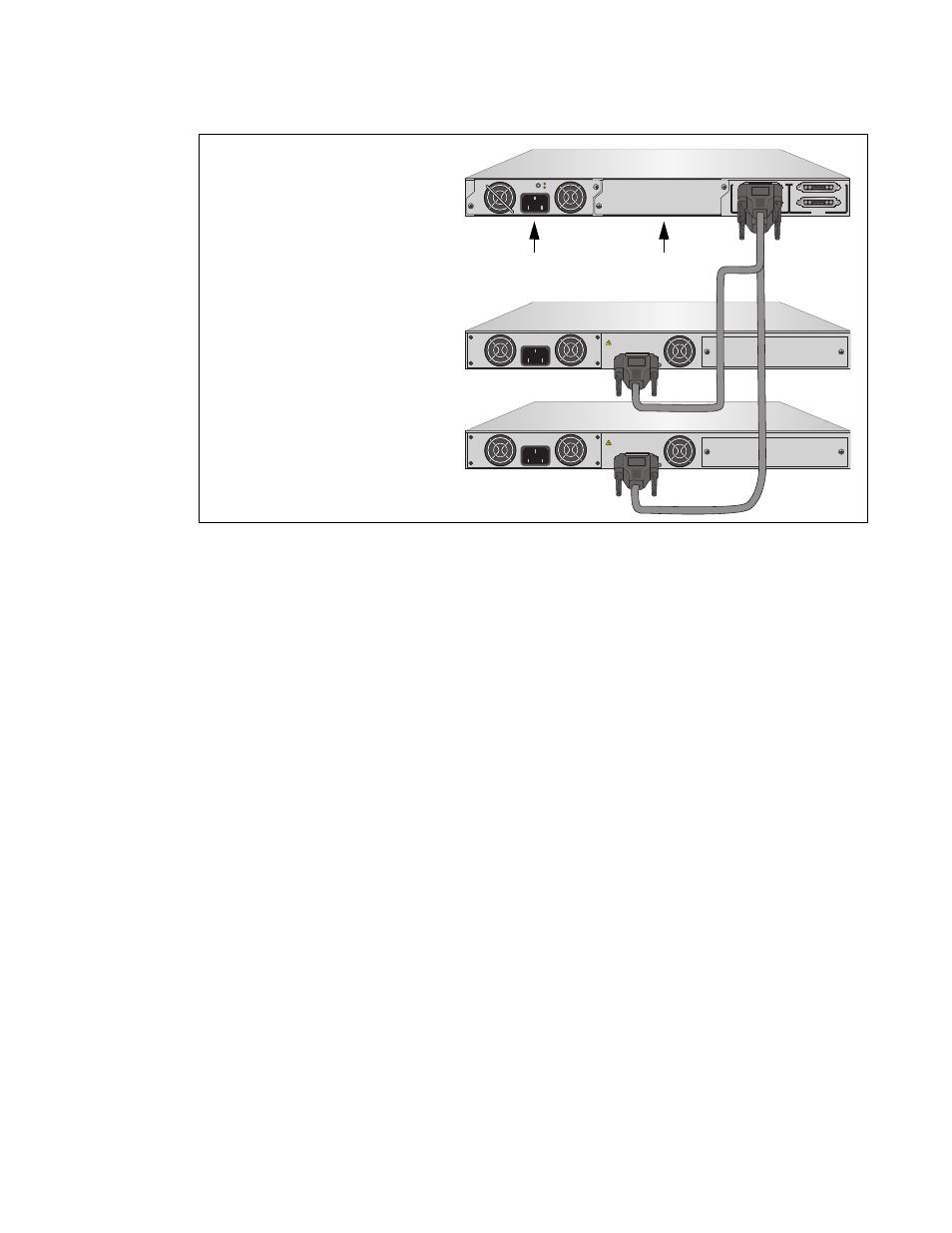
AT-RPS3000 Redundant Power Supply Installation Guide
35
Figure 19. Example of an Invalid Configuration - B
B
B
1
2
3
4
SYSTEM
PoE+ / SYSTEM
PoE+ / SYSTEM
SYSTEM
MODULE B
MODULE A
A
A
A
T
-PWR
8
00
DC OUT
FAULT
100-240 VAC~12A MAX
AT-PNL800/1200
100-240 VAC~12A MAX
PO
WER SUPPL
Y
RPS
READY
RPS INPUT
12V/21A MAX
WARNING
This unit may have more than one power input. To reduce the risk of
electric shock, disconnect both A/C and RPS inputs before servicing
unit.
100-240 VAC~12A MAX
PO
WER SUPPL
Y
RPS
READY
RPS INPUT
12V/21A MAX
WARNING
This unit may have more than one power input. To reduce the risk of
electric shock, disconnect both A/C and RPS inputs before servicing
unit.
2135
AT-x610-24Ts Switch
AT-x610-48Ts Switch
AT-RPS3000 Chassis
(Low-power)
(High-power)
with One Power Supply
Slot A
Slot B
- AT-GS908M (54 pages)
- AT-x230-10GP (80 pages)
- AT-GS950/48PS (64 pages)
- AT-GS950/10PS (386 pages)
- AT-GS950/16PS (386 pages)
- AT-GS950/48PS (386 pages)
- AT-9000 Series (258 pages)
- AT-9000 Series (1480 pages)
- IE200 Series (70 pages)
- AT-GS950/48 (60 pages)
- AT-GS950/48 (410 pages)
- AT-GS950/8 (52 pages)
- AT-GS950/48 (378 pages)
- SwitchBlade x8106 (322 pages)
- SwitchBlade x8112 (322 pages)
- SwitchBlade x8106 (240 pages)
- SwitchBlade x8112 (240 pages)
- AT-TQ Series (172 pages)
- AlliedWare Plus Operating System Version 5.4.4C (x310-26FT,x310-26FP,x310-50FT,x310-50FP) (2220 pages)
- FS970M Series (106 pages)
- 8100L Series (116 pages)
- 8100S Series (140 pages)
- x310 Series (116 pages)
- x310 Series (120 pages)
- AT-GS950/24 (404 pages)
- AT-GS950/24 (366 pages)
- AT-GS950/16 (44 pages)
- AT-GS950/16 (404 pages)
- AT-GS950/16 (364 pages)
- AT-GS950/8 (52 pages)
- AT-GS950/8 (404 pages)
- AT-GS950/8 (364 pages)
- AT-8100 Series (330 pages)
- AT-8100 Series (1962 pages)
- AT-FS970M Series (330 pages)
- AT-FS970M Series (1938 pages)
- SwitchBlade x3112 (294 pages)
- SwitchBlade x3106 (288 pages)
- SwitchBlade x3106 (260 pages)
- SwitchBlade x3112 (222 pages)
- AT-S95 CLI (AT-8000GS Series) (397 pages)
- AT-S94 CLI (AT-8000S Series) (402 pages)
- AT-IMC1000T/SFP (23 pages)
- AT-IMC1000TP/SFP (24 pages)
- AT-SBx3106WMB (44 pages)