Chapter 3: removing power supply modules 80, System poe+ / syst em poe+ / syste m system, Dc o ut fault – Allied Telesis AT-RPS3000 User Manual
Page 80: System poe+ / system poe+ / system system, Dc ou t fault
Chapter 3: Removing Power Supply Modules
80
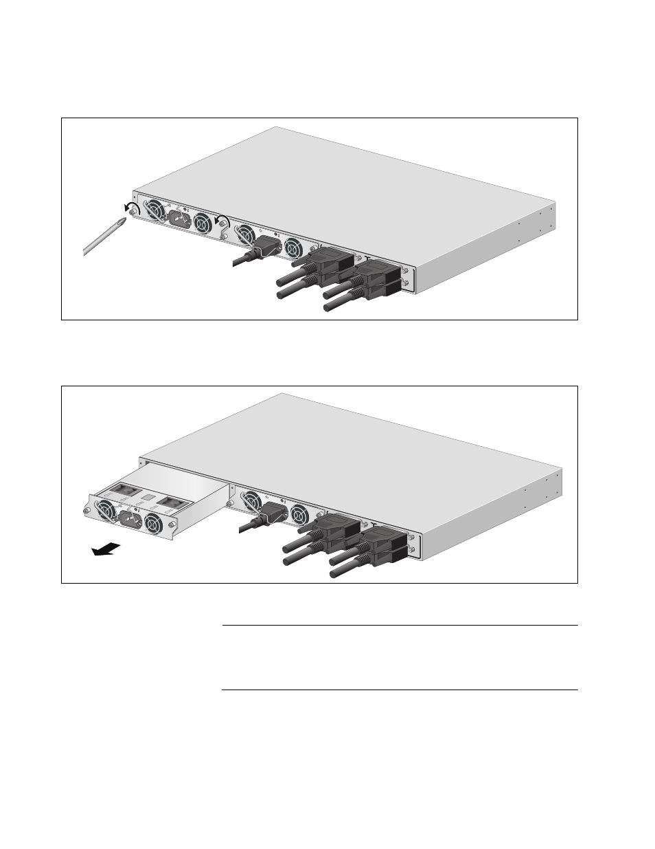
3. Loosen the two captive screws securing the power module to the
chassis.
Figure 60. Loosening the Two Captive Screws
4. Slide the module from the chassis.
Figure 61. Removing the Power Supply from the Chassis
Note
Use care when pulling the power supply module from the chassis.
You might bend the power and control pins on the backplane
connectors if you roughly pull the module from the unit.
5. To install a new power supply module, perform the procedure
“Installing a Power Supply Module” on page 61.
B
B
1
2
3
4
SYSTEM
PoE+ /
SYST
EM
PoE+ /
SYSTE
M
SYSTEM
MODULE B
MODULE A
A
A
A
T
-PWR
8
00
DC O
UT
FAULT
A
T
-PWR
8
00
DC OUT
FAULT
100-24
0 VAC~
12A M
AX
2171
100-24
0 VAC~
12A M
AX
B
B
1
2
3
4
SYSTEM
PoE+ /
SYSTEM
PoE+ /
SYSTEM
SYSTEM
MODULE B
MODULE A
A
A
A
T
-PWR
8
00
DC OUT
FAU
LT
100-24
0 VAC~
12A M
AX
A
T
-PWR
8
00
DC OU
T
FAULT
2172
100-24
0 VAC~
12A M
AX
- AT-GS908M (54 pages)
- AT-x230-10GP (80 pages)
- AT-GS950/48PS (64 pages)
- AT-GS950/10PS (386 pages)
- AT-GS950/16PS (386 pages)
- AT-GS950/48PS (386 pages)
- AT-9000 Series (258 pages)
- AT-9000 Series (1480 pages)
- IE200 Series (70 pages)
- AT-GS950/48 (378 pages)
- AT-GS950/48 (60 pages)
- AT-GS950/48 (410 pages)
- AT-GS950/8 (52 pages)
- SwitchBlade x8106 (322 pages)
- SwitchBlade x8112 (322 pages)
- SwitchBlade x8106 (240 pages)
- SwitchBlade x8112 (240 pages)
- AT-TQ Series (172 pages)
- AlliedWare Plus Operating System Version 5.4.4C (x310-26FT,x310-26FP,x310-50FT,x310-50FP) (2220 pages)
- FS970M Series (106 pages)
- 8100S Series (140 pages)
- 8100L Series (116 pages)
- x310 Series (116 pages)
- x310 Series (120 pages)
- AT-GS950/16 (44 pages)
- AT-GS950/24 (404 pages)
- AT-GS950/24 (366 pages)
- AT-GS950/16 (404 pages)
- AT-GS950/16 (364 pages)
- AT-GS950/8 (404 pages)
- AT-GS950/8 (364 pages)
- AT-GS950/8 (52 pages)
- AT-8100 Series (330 pages)
- AT-8100 Series (1962 pages)
- AT-FS970M Series (330 pages)
- AT-FS970M Series (1938 pages)
- SwitchBlade x3106 (288 pages)
- SwitchBlade x3112 (294 pages)
- SwitchBlade x3106 (260 pages)
- SwitchBlade x3112 (222 pages)
- AT-S95 CLI (AT-8000GS Series) (397 pages)
- AT-S94 CLI (AT-8000S Series) (402 pages)
- AT-IMC1000T/SFP (23 pages)
- AT-IMC1000TP/SFP (24 pages)
- AT-SBx3106WMB (44 pages)