Powering on the power supply modules, Figure 50: raising the power cord retaining clip, Dc o ut fault – Allied Telesis AT-RPS3000 User Manual
Page 69
AT-RPS3000 Redundant Power Supply Installation Guide
69
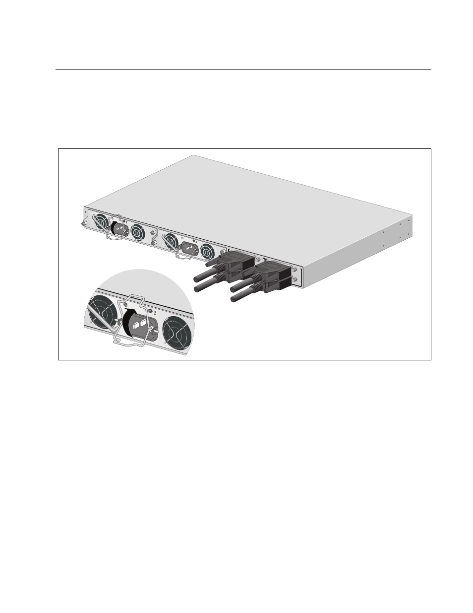
Powering On the Power Supply Modules
Perform this procedure to power on the power supply modules in the
AT-RPS3000 Chassis:
1. For the AT-PWR250 or AT-PWR800 Module, raise the power cord
retaining clip on the power supply module.
Figure 50. Raising the Power Cord Retaining Clip
2. Connect the AC power cord to the AC socket on the power supply
module, as shown in Figure 51 on page 70.
B
B
1
2
3
4
SYSTEM
PoE+ /
SYSTEM
PoE+ /
SYSTEM
SYSTEM
MODU
LE B
MODU
LE A
A
A
AT
-P
W
R
8
00
DC O
UT
FAULT
AT
-P
W
R
8
00
DC O
UT
FAULT
100-24
0 VAC~
12A M
AX
2164
100-24
0 VAC~
12A M
AX
DC O
UT
FAUL
T
100-240 V
AC~12A M
AX
See also other documents in the category Allied Telesis Computer hardware:
- AT-GS908M (54 pages)
- AT-x230-10GP (80 pages)
- AT-GS950/48PS (64 pages)
- AT-GS950/10PS (386 pages)
- AT-GS950/16PS (386 pages)
- AT-GS950/48PS (386 pages)
- AT-9000 Series (258 pages)
- AT-9000 Series (1480 pages)
- IE200 Series (70 pages)
- AT-GS950/48 (378 pages)
- AT-GS950/48 (60 pages)
- AT-GS950/48 (410 pages)
- AT-GS950/8 (52 pages)
- SwitchBlade x8106 (322 pages)
- SwitchBlade x8112 (322 pages)
- SwitchBlade x8106 (240 pages)
- SwitchBlade x8112 (240 pages)
- AT-TQ Series (172 pages)
- AlliedWare Plus Operating System Version 5.4.4C (x310-26FT,x310-26FP,x310-50FT,x310-50FP) (2220 pages)
- FS970M Series (106 pages)
- 8100L Series (116 pages)
- 8100S Series (140 pages)
- x310 Series (116 pages)
- x310 Series (120 pages)
- AT-GS950/24 (404 pages)
- AT-GS950/24 (366 pages)
- AT-GS950/16 (44 pages)
- AT-GS950/16 (404 pages)
- AT-GS950/16 (364 pages)
- AT-GS950/8 (364 pages)
- AT-GS950/8 (52 pages)
- AT-GS950/8 (404 pages)
- AT-8100 Series (330 pages)
- AT-8100 Series (1962 pages)
- AT-FS970M Series (330 pages)
- AT-FS970M Series (1938 pages)
- SwitchBlade x3106 (288 pages)
- SwitchBlade x3112 (294 pages)
- SwitchBlade x3106 (260 pages)
- SwitchBlade x3112 (222 pages)
- AT-S95 CLI (AT-8000GS Series) (397 pages)
- AT-S94 CLI (AT-8000S Series) (402 pages)
- AT-IMC1000T/SFP (23 pages)
- AT-IMC1000TP/SFP (24 pages)
- AT-SBx3106WMB (44 pages)