Choosing a power supply module, Non-poe+ switches – Allied Telesis AT-RPS3000 User Manual
Page 36
Chapter 1: Overview
36
Choosing a Power Supply Module
Here are a few suggestions on how to choose the power supply modules
for the x610 Series switches and AT-RPS3000 Chassis.
Non-PoE+
Switches
You may use any of the three available power supply modules listed in
Table 1 on page 19, even the two PoE+ modules, in the AT-RPS3000
Chassis to provide active system power to non-PoE+ switches. The
switches may be connected to any of the four RPS connectors on the
chassis.
A power module can support two low-power switches or one high-power
switch. For more information, refer to “Low-power and High-power
Switches” on page 24.
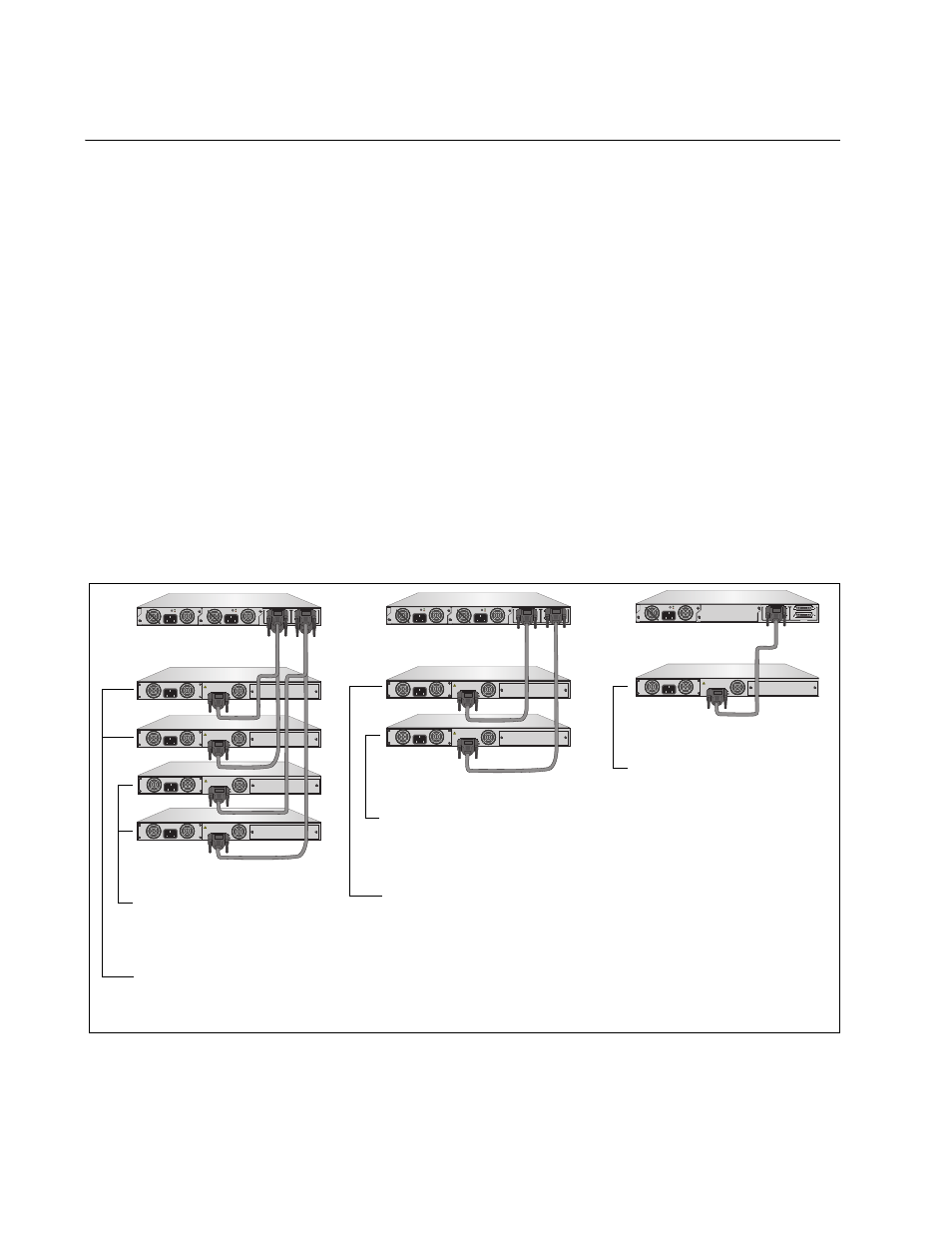
Here is an example. If you have five low-power and two high-power non-
PoE+ x610 Series switches, you would need five power modules, of any
model, and three chassis. The five low-power switches would need three
modules and the high-power switches two modules. The power modules
can be the same model, such as all AT-PWR800 Modules, or different
models.
Figure 20. Example of Power Modules and Non-PoE+ Switches
B
B
1
2
3
4
SYSTEM
PoE+ / SYSTEM
PoE+ / SYSTEM
SYSTEM
MODULE B
MODULE A
A
A
A
T
-PWR800
DC OUT
FAULT
100-240 VAC~12A MAX
A
T
-PWR800
DC OUT
FAULT
100-240 VAC~12A MAX
100-240 VAC~12A MAX
PO
WER
S
UPPL
Y
RPS
READY
RPS INPUT
12V/21A MAX
WARNING
This unit may have more than one power input. To reduce the risk of
electric shock, disconnect both A/C and RPS inputs before servicing
unit.
100-240 VAC~12A MAX
PO
WER
S
UPPL
Y
RPS
READY
RPS INPUT
12V/21A MAX
WARNING
This unit may have more than one power input. To reduce the risk of
electric shock, disconnect both A/C and RPS inputs before servicing
unit.
100-240 VAC~12A MAX
PO
WER
S
UPPL
Y
RPS
READY
RPS INPUT
12V/21A MAX
WARNING
This unit may have more than one power input. To reduce the risk of
electric shock, disconnect both A/C and RPS inputs before servicing
unit.
100-240 VAC~12A MAX
PO
WER
S
UPPL
Y
RPS
READY
RPS INPUT
12V/21A MAX
WARNING
This unit may have more than one power input. To reduce the risk of
electric shock, disconnect both A/C and RPS inputs before servicing
unit.
B
B
1
2
3
4
SYSTEM
PoE+ / SYSTEM
PoE+ / SYSTEM
SYSTEM
MODULE B
MODULE A
A
A
A
T
-PWR800
DC OUT
FAULT
100-240 VAC~12A MAX
A
T
-PWR800
DC OUT
FAULT
100-240 VAC~12A MAX
100-240 VAC~12A MAX
PO
WER
S
UPPL
Y
RPS
READY
RPS INPUT
12V/21A MAX
WARNING
This unit may have more than one power input. To reduce the risk of
electric shock, disconnect both A/C and RPS inputs before servicing
unit.
100-240 VAC~12A MAX
PO
WER
S
UPPL
Y
RPS
READY
RPS INPUT
12V/21A MAX
WARNING
This unit may have more than one power input. To reduce the risk of
electric shock, disconnect both A/C and RPS inputs before servicing
unit.
B
B
1
2
3
4
SYSTEM
PoE+ / SYSTEM
PoE+ / SYSTEM
SYSTEM
MODULE B
MODULE A
A
A
A
T
-PWR800
DC OUT
FAULT
100-240 VAC~12A MAX
AT-PNL800/1200
100-240 VAC~12A MAX
PO
WER
S
UPPL
Y
RPS
READY
RPS INPUT
12V/21A MAX
WARNING
This unit may have more than one power input. To reduce the risk of
electric shock, disconnect both A/C and RPS inputs before servicing
unit.
2211
Low-power, non-PoE+
switches powered by
the module in slot A.
Low-power, non-PoE+
switches powered by
the module in slot B.
Low-power, non-PoE+
switch powered by
the module in slot A.
High-power, non-PoE+
switch powered by
the module in slot B.
High-power, non-PoE+
switch powered by
the module in slot A.