Allied Telesis AT-RPS3000 User Manual
Page 65
AT-RPS3000 Redundant Power Supply Installation Guide
65
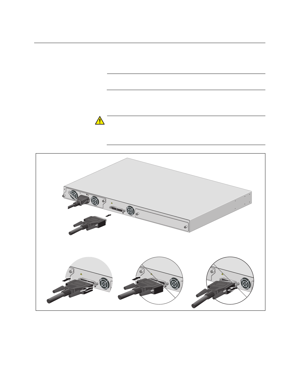
Connecting the AT-RPS3000 Chassis to the x610 Series Switch
Perform this procedure to connect the AT-RPS3000 Chassis to the x610
Series switch, with the AT-RPS-CBL1.0 cable:
Note
The AT-RPS-CBL1.0 cables must be purchased separately.
1. Connect one end of the RPS cable to the RPS Input connector on the
back panel of the switch.
Caution
Be sure to connect the RPS cable squarely and evenly on the
connector on the switch. Attaching the connector at an angle may
cause an electrical short that might damage the device.
Figure 45. Connecting the AT-RPS-CBL1.0 Cable to the x610 Series
Switch
STACKING
A
A
A
T
-PWR
8
00
DC O
UT
FAULT
PO
WER
S
UPPL
Y
RPS
READY
RPS IN
PUT
WARNIN
G
This uni
t may h
ave mor
e than o
ne pow
er input.
To redu
ce the ri
sk of
electric
shock, d
isconne
ct both A
/C and R
PS inpu
ts before
servicin
g
unit.
12V/21
A MAX
2132
PO
WER
S
UPPL
Y
RPS
REA
DY
RPS INP
UT
WARNIN
G
This unit m
ay have
more th
an one p
ower in
put. To
reduce
the ris
k of
electric
shock, d
isconne
ct both A
/C and R
PS inpu
ts befo
re servic
ing
unit.
12V/21A
MAX
PO
WER
S
UPPL
Y
RPS
REA
DY
RPS INP
UT
WARNIN
G
This uni
t may h
ave mor
e than
one po
wer in
put. To
reduce
the risk
of
electric
shock,
disconn
ect both
A/C and
RPS in
puts be
fore ser
vicing
unit.
12V/21A
MAX
PO
WER
S
UPPL
Y
RPS
REA
DY
RPS INP
UT
WARNIN
G
This unit m
ay have
more th
an one p
ower in
put. To
reduce
the ris
k of
electric
shock, d
isconne
ct both
A/C and
RPS in
puts be
fore ser
vicing
unit.
12V/21A
MAX
100-240
VAC~12A
MAX