Cable led port on/off button – Allied Telesis AT-RPS3000 User Manual
Page 66
Chapter 2: Installing the AT-RPS3000 Chassis and Power Supply Modules
66
2. Secure the cable to the switch by tightening the two thumbscrews.
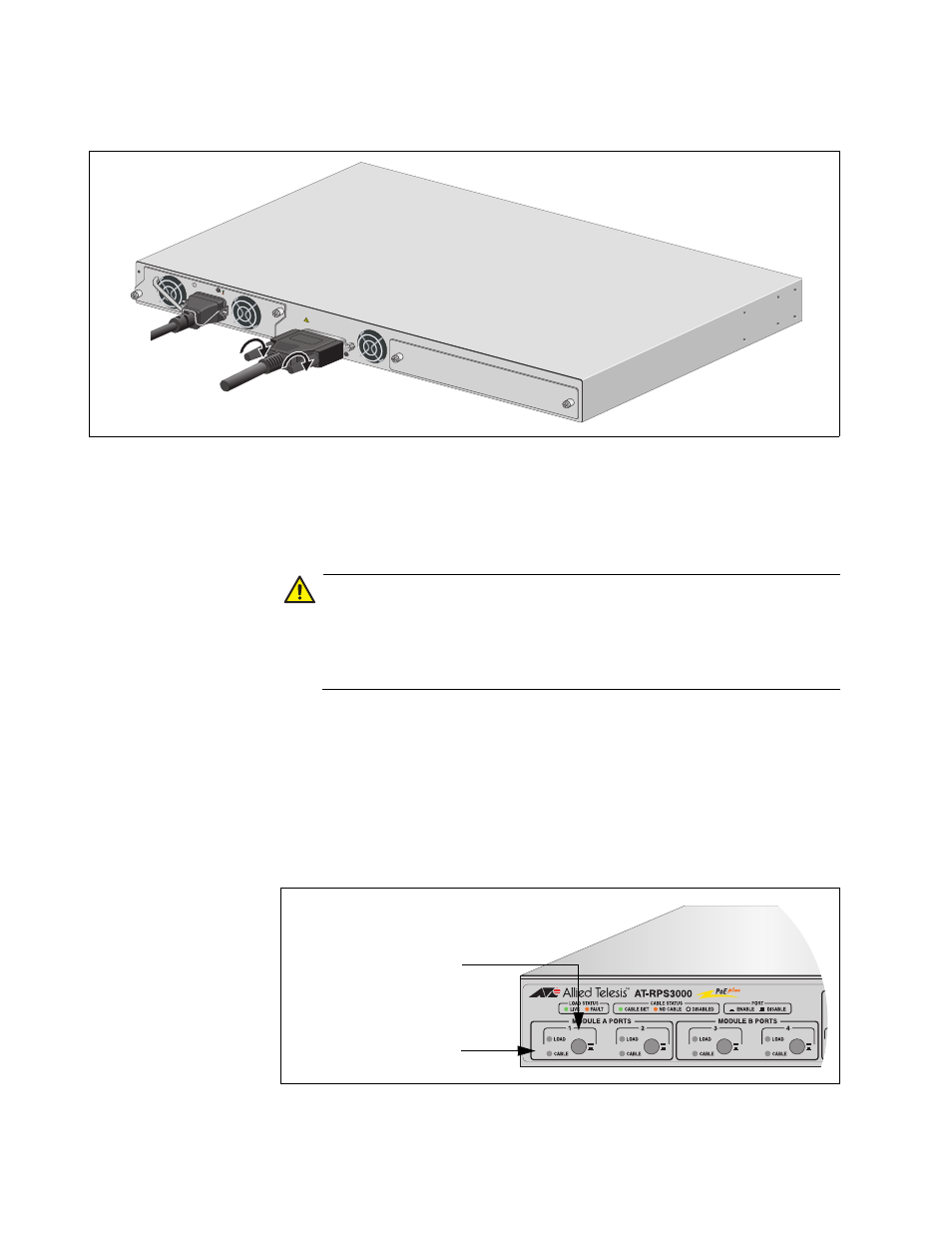
Figure 46. Securing the AT-RPS-CBL1.0 Cable to the Switch
If the AT-RPS3000 Chassis is already operational, perform step 3 to
turn off the RPS port before connecting the RPS cable. Otherwise, go
to step 4.
Caution
Never connect or disconnect an RPS cable from an RPS port on an
operational AT-RPS3000 Chassis without first turning off the port.
Failure to disable an RPS port may damage the redundant power
supply system.
3. On the front panel of the AT-RPS3000 Chassis, examine the CABLE
LED that corresponds to the port to which you will connect the cable. If
the LED is off, go to the next step. If the LED is green, press the On/
Off button to turn off the port. The LED should turn off.
For example, if you intend to connect the DC RPS cable to port 3 on
the AT-RPS3000 Chassis, check the CABLE LED for port 3. If the LED
is on, press the port’s On/Off button to disable the port.
Figure 47. RPS Port On/Off Buttons and CABLE LEDs
STACK
ING
AT
-P
W
R
8
00
DC P
OWER
FAUL
T
100-240
VAC~1
2A M
AX
PO
WER
S
UPPL
Y
RPS
READY
RPS IN
PUT
WARNIN
G
This unit
may
have
more tha
n one p
ower in
put. To
reduce
the risk
of
electric
shock, d
isconne
ct both
A/C and
RPS in
puts be
fore ser
vicin
g
unit.
2133
2161
CABLE LED
Port On/Off Button