Figure 53: lowering the power cord retaining clip, Dc out fault – Allied Telesis AT-RPS3000 User Manual
Page 71
AT-RPS3000 Redundant Power Supply Installation Guide
71
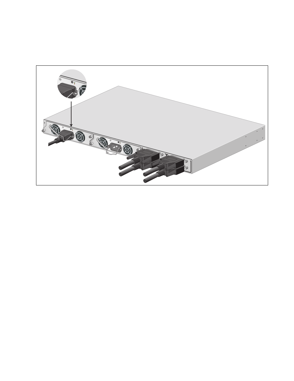
5. Examine the DC OUT/FAULT LED on the power supply module. The
module is operating normally if the LED is green. If the LED is amber
or off, refer to Chapter 4, “Troubleshooting” on page 83 for
troubleshooting suggestions.
Figure 53. Lowering the Power Cord Retaining Clip
6. In the POWER MODULE STATUS section of the LED panel shown in
Figure 54 on page 72, examine the FAN and DC OUT LEDs of the
power supply module you just powered on. Both LEDs should be
green. If the LEDs are amber or off, refer to Chapter 4,
“Troubleshooting” on page 83 for troubleshooting suggestions.
B
B
1
2
3
4
SYSTEM
PoE+ /
SYSTEM
PoE+ /
SYSTEM
SYSTEM
MODU
LE B
MODU
LE A
A
A
A
T
-PWR
8
00
DC OUT
FAULT
A
T
-PWR
8
00
DC OUT
FAULT
2147
100-240 V
AC~12A
MAX
100-240
VAC~12A
MAX
DC O
UT
FAUL
T
100-24
0 VAC~
12A M
AX
- AT-GS908M (54 pages)
- AT-x230-10GP (80 pages)
- AT-GS950/48PS (64 pages)
- AT-GS950/10PS (386 pages)
- AT-GS950/16PS (386 pages)
- AT-GS950/48PS (386 pages)
- AT-9000 Series (258 pages)
- AT-9000 Series (1480 pages)
- IE200 Series (70 pages)
- AT-GS950/48 (60 pages)
- AT-GS950/48 (410 pages)
- AT-GS950/8 (52 pages)
- AT-GS950/48 (378 pages)
- SwitchBlade x8106 (322 pages)
- SwitchBlade x8112 (322 pages)
- SwitchBlade x8106 (240 pages)
- SwitchBlade x8112 (240 pages)
- AT-TQ Series (172 pages)
- AlliedWare Plus Operating System Version 5.4.4C (x310-26FT,x310-26FP,x310-50FT,x310-50FP) (2220 pages)
- FS970M Series (106 pages)
- 8100L Series (116 pages)
- 8100S Series (140 pages)
- x310 Series (116 pages)
- x310 Series (120 pages)
- AT-GS950/24 (404 pages)
- AT-GS950/24 (366 pages)
- AT-GS950/16 (44 pages)
- AT-GS950/16 (404 pages)
- AT-GS950/16 (364 pages)
- AT-GS950/8 (364 pages)
- AT-GS950/8 (52 pages)
- AT-GS950/8 (404 pages)
- AT-8100 Series (330 pages)
- AT-8100 Series (1962 pages)
- AT-FS970M Series (330 pages)
- AT-FS970M Series (1938 pages)
- SwitchBlade x3112 (294 pages)
- SwitchBlade x3106 (288 pages)
- SwitchBlade x3106 (260 pages)
- SwitchBlade x3112 (222 pages)
- AT-S95 CLI (AT-8000GS Series) (397 pages)
- AT-S94 CLI (AT-8000S Series) (402 pages)
- AT-IMC1000T/SFP (23 pages)
- AT-IMC1000TP/SFP (24 pages)
- AT-SBx3106WMB (44 pages)