Figure 10: example of four low-power switches – Allied Telesis AT-RPS3000 User Manual
Page 27
AT-RPS3000 Redundant Power Supply Installation Guide
27
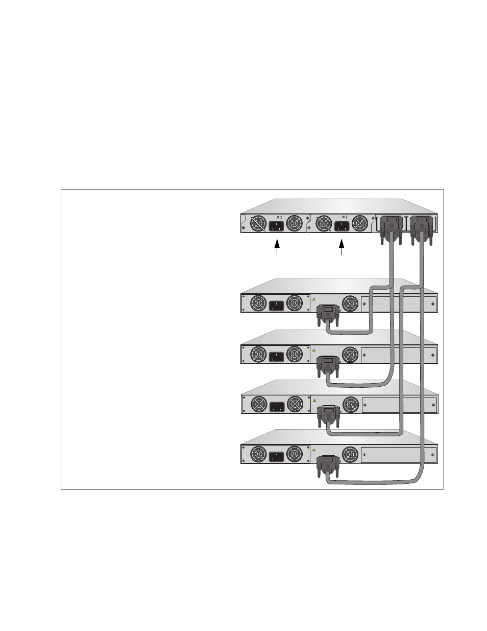
The chassis must have a second power supply to support three or four
low-power switches, as illustrated in the following example. The power
module in slot A supports switches 1 and 2, and the module in slot B
powers switches 3 and 4.
The power supply modules in the chassis may be the same or different
models. For instance, you might install two AT-PWR250 Modules or
perhaps two AT-PWR1200 Modules. You may also combine the
AT-PWR800 and AT-PWR1200 Modules in the chassis, installing one of
each model in the slots. However, you may not combine the AT-PWR250
Module with the AT-PWR800 or AT-PWR1200 Module in the chassis, as
explained in “Power Supply Modules” on page 19.
Figure 10. Example of Four Low-power Switches
1. AT-x610-24Ts Switch
2. AT-x610-24Ts Switch
AT-RPS3000 Chassis
with Two Power Supplies
3. AT-x610-24Ts Switch
4. AT-x610-24Ts/X Switch
B
B
1
2
3
4
SYSTEM
PoE+ / SYSTEM
PoE+ / SYSTEM
SYSTEM
MODULE B
MODULE A
A
A
A
T
-PWR
8
00
DC OUT
FAULT
100-240 VAC~12A MAX
A
T
-PWR
8
00
DC POWER
FAULT
100-240 VAC~12A MAX
100-240 VAC~12A MAX
PO
WER SUPPL
Y
RPS
READY
RPS INPUT
12V/21A MAX
WARNING
This unit may have more than one power input. To reduce the risk of
electric shock, disconnect both A/C and RPS inputs before servicing
unit.
100-240 VAC~12A MAX
PO
WER SUPPL
Y
RPS
READY
RPS INPUT
12V/21A MAX
WARNING
This unit may have more than one power input. To reduce the risk of
electric shock, disconnect both A/C and RPS inputs before servicing
unit.
100-240 VAC~12A MAX
PO
WER SUPPL
Y
RPS
READY
RPS INPUT
12V/21A MAX
WARNING
This unit may have more than one power input. To reduce the risk of
electric shock, disconnect both A/C and RPS inputs before servicing
unit.
100-240 VAC~12A MAX
PO
WER SUPPL
Y
RPS
READY
RPS INPUT
12V/21A MAX
WARNING
This unit may have more than one power input. To reduce the risk of
electric shock, disconnect both A/C and RPS inputs before servicing
unit.
2138
Slot A
Slot B
Low-power, Non-PoE+ Switches
Powered by the Module in Slot A
Low-power, Non-PoE+ Switches
Powered by the Module in Slot B