Configuration examples, Low-power switches – Allied Telesis AT-RPS3000 User Manual
Page 25
AT-RPS3000 Redundant Power Supply Installation Guide
25
Configuration Examples
The following examples illustrate different configurations of the chassis,
switches, and power supply modules.
Low-power
Switches
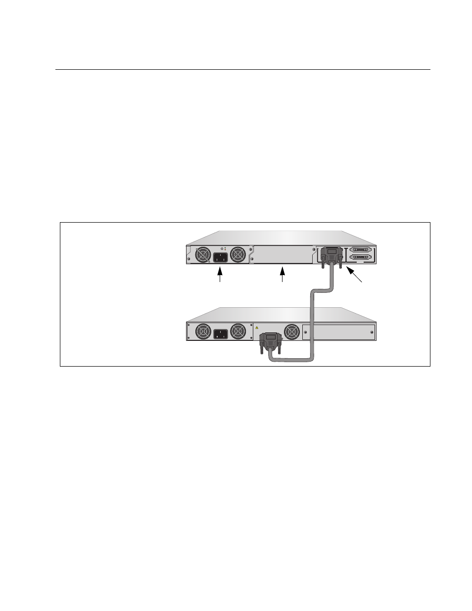
In the first example, the AT-RPS3000 Chassis, with one power supply
module in slot A, is supporting a single low-power switch, connected to the
RPS 1 System port. (The RPS 3 System and RPS 4 PoE+/System ports
do not have power because slot B is empty.) The non-PoE+ AT-x610-24Ts
Switch places its non-removable, internal power supply module in a
redundant state, and receives all of its system power from the
AT-RPS3000 Chassis and the power module in slot A. If there is an
interruption of system power from the chassis, the switch automatically
activates its internal power supply to maintain network operations.
Figure 7. Example of a Single Low-power Switch Connected to an RPS
System Port
It should be noted that even though the switch in the example is a non-
PoE+ model, the power supply module in slot A can be any of the three
available power modules, including the AT-PWR800 and AT-PWR1200
Modules. The three modules may be used to provide system power to
PoE+ and non-PoE+ switches.
Non-PoE+ switches may be connected to either the RPS System or PoE+/
System port on the chassis. Non-PoE+ switches connected to an RPS
PoE+/System port receive system power, but no power for PoE+, even if
the power supply in the corresponding slot in the chassis contains a PoE+
module. This principal is illustrated in Figure 8 on page 26 where the single
low-power, non-PoE+ switch from the previous example is now connected
to the RPS 2 PoE+/System port, from which it receives just system power.
B
B
1
2
3
4
SYSTEM
PoE+ / SYSTEM
PoE+ / SYSTEM
SYSTEM
MODULE B
MODULE A
A
A
A
T
-PWR
8
00
DC OUT
FAULT
100-240 VAC~12A MAX
AT-PNL800/1200
100-240 VAC~12A MAX
PO
WER SUPPL
Y
RPS
READY
RPS INPUT
12V/21A MAX
WARNING
This unit may have more than one power input. To reduce the risk of
electric shock, disconnect both A/C and RPS inputs before servicing
unit.
2140
AT-x610-24Ts Switch
AT-RPS3000 Chassis
(Low-power)
with One Power Supply
Slot A
Slot B
RPS 1
System Port