Invalid configurations – Allied Telesis AT-RPS3000 User Manual
Page 33
AT-RPS3000 Redundant Power Supply Installation Guide
33
Figure 17. Example of Low-power PoE+ and Non-PoE+ Switches
Invalid
Configurations
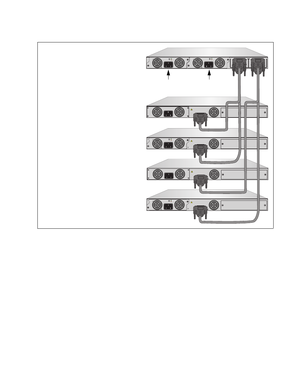
Here are examples of invalid configurations. In the first example in Figure
18 on page 34, two low-power, non-PoE+ switches are connected to RPS
1 and 3 System ports on a chassis that has one power module in slot A.
While it is true that you may use one power supply module to supply
system power to two low-power switches, you have to be sure to connect
the switches to the correct ports. The power supply module in slot A
delivers power to RPS 1 and 2 ports. RPS 3 and 4 ports are not receiving
any power because slot B is empty. To correct the problem, you could
connect the AT-x610-24Ts/X Switch to RPS 2 PoE+/System port on the
chassis or install another power supply module.
PO
WER SUPPL
Y
RPS
READY
RPS INPUT
12V/21A MAX
WARNING
This unit may have more than one power input. To reduce the risk of
electric shock, disconnect both A/C and RPS inputs before servicing
unit.
100-240 VAC~12A MAX
100-240 VAC~12A MAX
PO
WER SUPPL
Y
RPS
READY
RPS INPUT
12V/21A MAX
WARNING
This unit may have more than one power input. To reduce the risk of
electric shock, disconnect both A/C and RPS inputs before servicing
unit.
PO
WER SUPPL
Y
RPS
READY
RPS INPUT
12V/21A MAX
WARNING
This unit may have more than one power input. To reduce the risk of
electric shock, disconnect both A/C and RPS inputs before servicing
unit.
A
T
-PWR
8
00
DC OUT
FAULT
100-240 VAC~12A MAX
B
B
1
2
3
4
SYSTEM
PoE+ / SYSTEM
PoE+ / SYSTEM
SYSTEM
MODULE B
MODULE A
A
A
A
T
-PWR
8
00
DC OUT
FAULT
100-240 VAC~12A MAX
A
T
-PWR
8
00
DC OUT
FAULT
100-240 VAC~12A MAX
PO
WER SUPPL
Y
RPS
READY
RPS INPUT
12V/21A MAX
WARNING
This unit may have more than one power input. To reduce the risk of
electric shock, disconnect both A/C and RPS inputs before servicing
unit.
2211
A
T
-PWR
8
00
DC OUT
FAULT
100-240 VAC~12A MAX
AT-x610-24Ts Switch
AT-x610-24Ts-POE+ Switch
AT-RPS3000 Chassis
(Low-power)
(Low-power)
with Two Power Supplies
Slot A
Slot B
AT-x610-24Ts/X Switch
AT-x610-24Ts/X-POE+ Switch
(Low-power)
(Low-power)
Switches supported by the Power
Module in Slot A.
Switches supported by the Power
Module in Slot B.