Allied Telesis AT-RPS3000 User Manual
Page 32
Chapter 1: Overview
32
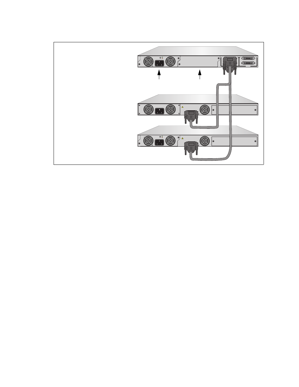
Figure 16. Example of Low-power PoE+ and Non-PoE+ Switches
The AT-PWR800 or AT-PWR1200 Module in slot A is performing three
functions for the two switches. It is acting as the active source of system
power for the AT-x610-24Ts Switch connected to RPS 1 System port, as a
redundant source of system power for the AT-x610-24Ts-POE+
connected to the RPS 2 PoE+/System port, and as an active source of
addition PoE+ power for the PoE+ switch.
The example in Figure 17 on page 33 builds on the previous example,
adding a power supply module to slot B and two more low power PoE+
and non-PoE+ switches.
B
B
1
2
3
4
SYSTEM
PoE+ / SYSTEM
PoE+ / SYSTEM
SYSTEM
MODULE B
MODULE A
A
A
A
T
-PWR
8
00
DC OUT
FAULT
100-240 VAC~12A MAX
AT-PNL800/1200
100-240 VAC~12A MAX
PO
WER SUPPL
Y
RPS
READY
RPS INPUT
12V/21A MAX
WARNING
This unit may have more than one power input. To reduce the risk of
electric shock, disconnect both A/C and RPS inputs before servicing
unit.
PO
WER SUPPL
Y
RPS
READY
RPS INPUT
12V/21A MAX
WARNING
This unit may have more than one power input. To reduce the risk of
electric shock, disconnect both A/C and RPS inputs before servicing
unit.
A
T
-PWR
8
00
2144
DC OUT
FAULT
100-240 VAC~12A MAX
AT-x610-24Ts Switch
AT-x610-24Ts/X-POE+ Switch
AT-RPS3000 Chassis
(Low-power)
(Low-power)
with One Power Supply
Slot A
Slot B