Dc out fault – Allied Telesis AT-RPS3000 User Manual
Page 77
AT-RPS3000 Redundant Power Supply Installation Guide
77
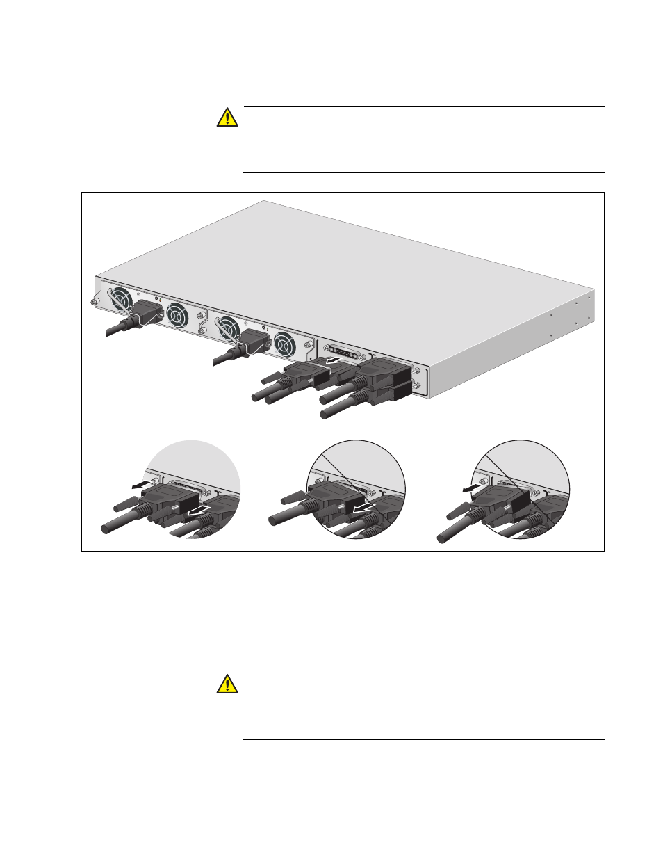
3. Remove the cable from the RPS port.
Caution
Be sure to remove the RPS cable squarely and evenly from the
connector on the chassis. Removing the connector at an angle may
cause an electrical short that might damage the device.
Figure 57. Removing the AT-RPS-CBL1.0 Cable from the AT-RPS3000
Chassis
4. Loosen the two thumbscrews that secure the cable to the RPS port on
the x610 Series switch.
5. Remove the cable from the RPS port on the switch.
Caution
Be sure to remove the RPS cable squarely and evenly from the
connector on the switch. Removing the connector at an angle may
cause an electrical short that might damage the device.
B
B
1
2
3
4
PoE+ /
SYSTEM
PoE+ /
SYSTEM
SYSTEM
MODU
LE B
MODU
LE A
A
T
-PWR
8
00
DC OUT
FAULT
100-240 V
AC~12A
MAX
A
T
-PWR
8
00
DC OUT
FAULT
2211
100-240 V
AC~12A
MAX
SYSTEM
B
B
1
2
SYSTEM
PoE+ /
SYSTEM
Po
M
MODU
LE A
B
B
1
2
SYSTEM
PoE+ /
SYSTEM
Po
M
MODU
LE A
B
B
1
2
SYSTEM
PoE+ /
SYSTEM
Po
M
MODU
LE A
- AT-GS908M (54 pages)
- AT-x230-10GP (80 pages)
- AT-GS950/48PS (64 pages)
- AT-GS950/10PS (386 pages)
- AT-GS950/16PS (386 pages)
- AT-GS950/48PS (386 pages)
- AT-9000 Series (258 pages)
- AT-9000 Series (1480 pages)
- IE200 Series (70 pages)
- AT-GS950/8 (52 pages)
- AT-GS950/48 (378 pages)
- AT-GS950/48 (60 pages)
- AT-GS950/48 (410 pages)
- SwitchBlade x8106 (322 pages)
- SwitchBlade x8112 (322 pages)
- SwitchBlade x8106 (240 pages)
- SwitchBlade x8112 (240 pages)
- AT-TQ Series (172 pages)
- AlliedWare Plus Operating System Version 5.4.4C (x310-26FT,x310-26FP,x310-50FT,x310-50FP) (2220 pages)
- FS970M Series (106 pages)
- 8100S Series (140 pages)
- 8100L Series (116 pages)
- x310 Series (116 pages)
- x310 Series (120 pages)
- AT-GS950/24 (366 pages)
- AT-GS950/16 (44 pages)
- AT-GS950/24 (404 pages)
- AT-GS950/16 (404 pages)
- AT-GS950/16 (364 pages)
- AT-GS950/8 (404 pages)
- AT-GS950/8 (364 pages)
- AT-GS950/8 (52 pages)
- AT-8100 Series (330 pages)
- AT-8100 Series (1962 pages)
- AT-FS970M Series (1938 pages)
- AT-FS970M Series (330 pages)
- SwitchBlade x3106 (288 pages)
- SwitchBlade x3112 (294 pages)
- SwitchBlade x3106 (260 pages)
- SwitchBlade x3112 (222 pages)
- AT-S95 CLI (AT-8000GS Series) (397 pages)
- AT-S94 CLI (AT-8000S Series) (402 pages)
- AT-IMC1000T/SFP (23 pages)
- AT-IMC1000TP/SFP (24 pages)
- AT-SBx3106WMB (44 pages)