Av1410, Installation – Audiovox AV1410 User Manual
Page 6
AV1410
2
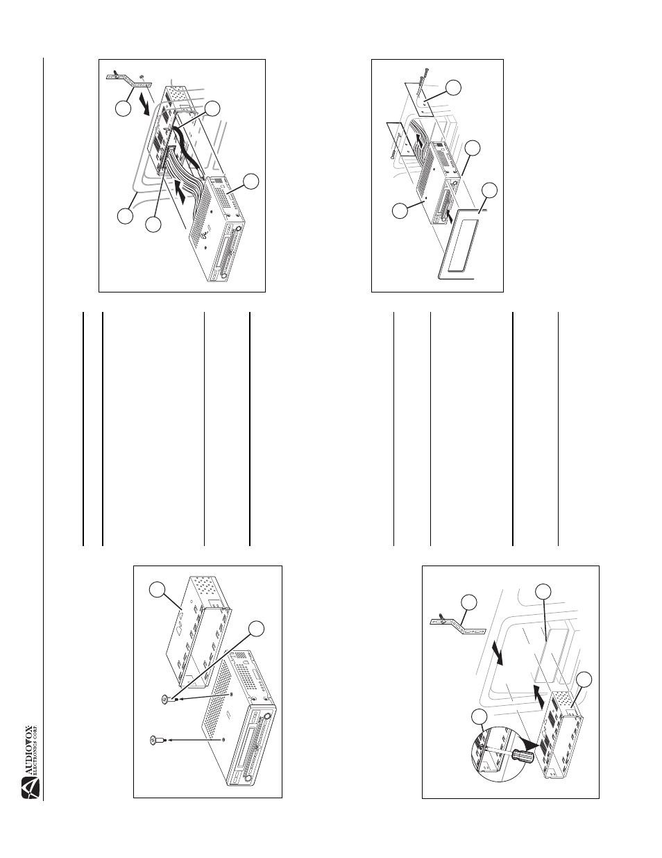
INSTALLATION
Pre-
in
stallatio
n
1.
Press t
he met
a
l lever
s
on b
o
th sides to r
e
move
the half-
sleeve fro
m
the radio.
2.
Remove the tr
ansport scr
e
ws.
3.
Inst
all the ha
lf-
s
leeve.
a.
Inst
all adapt
er if necessary (o
ptiona
l)
.
b.
Inst
all half-sleeve into ad
apter or
dashboard
(only
use the supplied screws). D
o
not for
c
e the
sleeve
int
o
the opening or
cau
s
e it to bend
or bow
.
c.
Locate the series of bend t
a
bs along th
e top,
bottom and
sides of the mounting sleeve.
With the
sleeve fully inser
ted into the dashboar
d opening,
bend as many of the t
a
b
s
outwa
rd as
necessa
ry
so
that the sleeve
is firmly secured to th
e dashboard.
d.
Inst
all support
str
ap to make the unit mor
e
st
able.
CAU
TION! B
e
carefu
l no
t to
dam
a
ge
the
car wirin
g
.
4.
Pla
c
e
the r
adio
in
front
of the
dashboard
opening so
the
wiring can be br
ought thr
ough the moun
ting sleeve
.
Wiring
Complete wiring as illust
rated in the w
ir
ing diagr
am on p
age
3. Once the wiring is complete, reconnect the
battery
negative terminal. If there
is
no ACC
availa
ble, connect the
ACC lead to th
e power
supp
ly with a switch.
NOTE:
Wh
en rep
lacing
a fu
se, b
e
sure t
o
u
se correct
typ
e
an
d am
perage
to a
v
oid
dam
a
gin
g
th
e radio
. Th
e
A
V
1410
uses o
n
e 10
amp
min
i-A
T
M
fu
se, loc
a
ted
in th
e
bla
ck filt
er box
in-li
n
e with
the
main
wire h
a
rness.
Fi
nal Instal
lation
Af
ter
completing the wiring connections, t
u
rn the u
n
it on
to
confir
m opera
tion (
ign
ition switch must be on)
. If unit does not
oper
ate, recheck all wiring until pr
oblem is corre
cted.
Once
pro
per oper
ation is achie
v
ed, tu
rn of
f the ignition switch and
pro
c
eed w
ith f
inal mounting of the
chassis.
1.
Conne
ct w
iring ada
pter to e
x
isting wiring har
ness.
2.
Conne
ct ant
enna lead.
3.
Car
e
fully
slide the r
adio in
to the half-sleeve making sure
it is right-side-up
until it
is fully seated and the
spr
ing
cl
ip
s l
o
ck i
t into place.
NOTE:
For p
rope
r o
p
erat
ion
of t
h
e C
D
/DVD p
layer
, the
cha
ssis mu
st b
e
mo
un
ted
wit
h
in
20° o
f ho
rizo
nt
al. Make
sure the u
n
it is mo
un
ted
within
thi
s
limitatio
n.
4.
Att
a
ch one end
of the per
forated
suppo
rt strap
(supplie
d) to the
screw
stud o
n
the rea
r of the chassis
using
the hex nut pro
v
ided. F
a
sten
the other
end of the
per
forated
str
ap t
o
a
secure
p
a
rt
of
the dashboar
d either
above or
below
the rad
io using the scr
e
w and h
e
x nu
t
pro
v
ided. Bend the
str
ap to position it as necessar
y.
C
A
U
T
ION
! Th
e
re
a
r of
th
e
ra
d
io
m
u
s
t be
s
u
pp
ort
e
d w
ith
th
e strap
to
preven
t da
mag
e
to
the d
ash
board
from
th
e
w
e
igh
t of
th
e radio
or im
prop
er op
era
tion
du
e to
vib
rat
ion
.
5.
Rep
lace any ite
m
s you r
e
moved
from the d
a
shbo
ard.
Fin
a
l ISO-DI
N Installation
1.
Remo
ve trim ring
.
2.
Mount
factor
y b
racket
s
on
new rad
io using existing
scr
e
ws from old r
adio.
3.
Slide r
adio cha
s
sis into dash opening and secure.
4.
Reinst
all dash p
a
nel.
2
1
7-INCH
TFT
7-INCH
TF
T
MODE
VM9510
MUTE
AS/PS
BAND
DISP
PWR
ENTER
AM/FM/DVD/MP3
RECEIVER
7-INCH
DIGIT
AL
TFT
OPEN
Pu
sh
Pu
sh
AV
AU
XI
N
PREP
AR
E RADIO
3d
3a
3b
3c
IN
ST
AL
L HA
LF SL
EEVE
2
1
3
4
7-INCH
TFT
7-INCH
TF
T
MODE
VM9510
MUTE
AS/PS
BAND
DISP
PWR
ENTER
AM/FM/DVD/MP3
RECEIVER
7-INCH
DIGIT
AL
TFT
OPEN
Pu
sh
Pu
sh
AV
AU
X
IN
5
FIN
A
L IN
ST
AL
LA
T
IO
N
3
4
7-INCH
TF
T
7-INCH
TF
T
MODE
VM9510
MUTE
AS/PS
BAND
DISP
PWR
ENTER
AM/FM/DVD/MP3
RECEIVER
7-INCH
DIGIT
AL
TF
T
OPEN
Pu
sh
Pu
sh
AV
AU
X
IN
2
1
F
INAL
ISO-
DIN IN
ST
AL
LA
T
ION