Wesley BC-620-4CA User Manual
Page 56
52
Curtis 1234/36/38 Manual,
OS
11
3 — PROGRAMMABLE PARAMETERS:
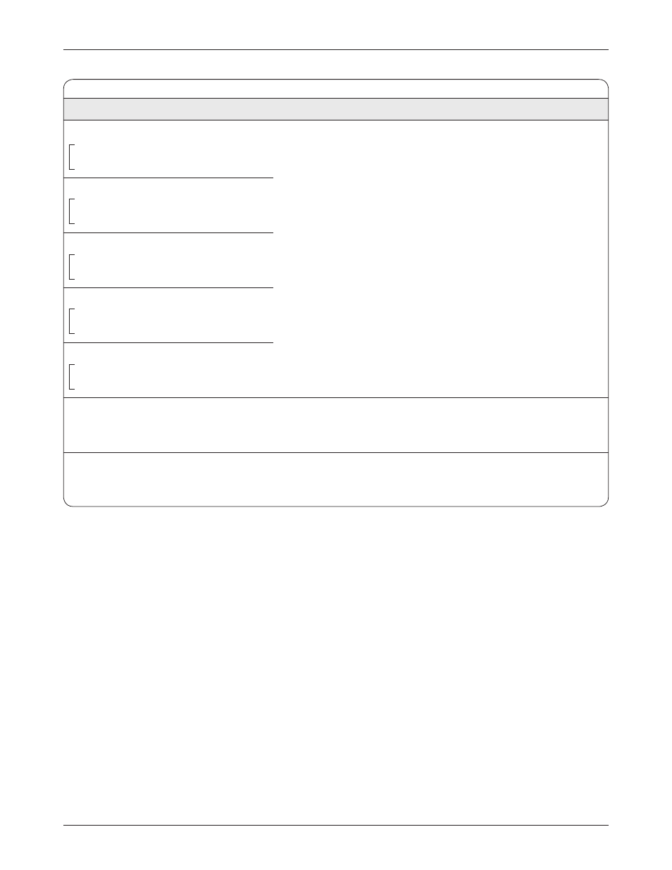
Fault Checking Parameters
FAULT CHECKING MENU
ALLOWABLE
PARAMETER
RANGE
DESCRIPTION
Driver1 Checks Enable
On/Off
C
Driver1_Checks_Enable
On/Off
OptionBits2 [Bit 1]
Driver2 Checks Enable
On/Off
S
Driver2_Checks_Enable
On/Off
OptionBits2 [Bit 2]
Driver3 Checks Enable
On/Off
S
Driver3_Checks_Enable
On/Off
OptionBits2 [Bit 3]
Driver4 Checks Enable
On/Off
S
Driver4_Checks_Enable
On/Off
OptionBits2 [Bit 4]
PD Checks Enable
On/Off
S
PD_Checks_Enable
On/Off
OptionBits2 [Bit 5]
External Supply Max
5–200 mA
Sets the upper threshold of the combined current of the 5V and 12V
External_Supply_Max
52–800
external supplies. At or above this threshold a fault will be created that
can be read by VCL.
External Supply Min
5–200 mA
Sets the lower threshold of the combined current of the 5V and 12V
External_Supply_Min
52–800
external supplies. At or below this threshold a fault will be created that
can be read by VCL.
The five Checks Enable parameters are used to enable driver
and coil fault detection at the five individual drivers (at Pins
J1-6, J1-5, J1-4, J1-3, and J1-2). When a Checks parameter
is enabled, the associated driver, driver wiring, and driver load
are checked to verify that the driver correctly drives the load
both high and low. The checks will occur regardless of the PWM
output of the driver. The checks will detect both open and shorted
conditions. When a fault is detected, the controller opens the
driver and issues a fault code.
If nothing is connected to a driver, its Checks Enable
parameter should be set Off.
Note: Short circuit protection is always active at these five
drivers, regardless of how Checks Enable is set.