Wesley BC-620-4CA User Manual
Page 16
12
Curtis 1234/36/38 Manual,
OS
11
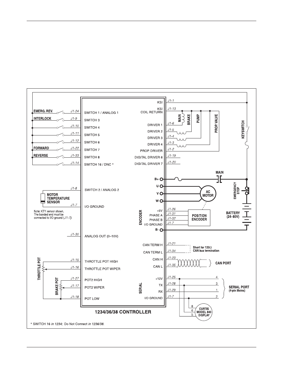
Fig. 3
Basic wiring diagram, Curtis 1234/36/38 motor controller.
2 — INSTALLATION & WIRING:
Standard Wiring Diagram
CONTROLLER WIRING: BASIC CONFIGURATION
A basic wiring diagram is shown in Figure 3. Throttle and brake are shown in
the diagram as 3-wire potentiometers; other types of throttle and brake inputs
are easily accommodated, and are discussed in the following throttle wiring
section.
The main contactor coil must be wired directly to the controller as shown
in Figure 3 to meet EEC safety requirements. The controller can be programmed
This manual is related to the following products: