14 pressure transducer - 4 wire full bridge – Campbell Scientific CR7 Measurement and Control System User Manual
Page 78
SECTION 7. MEASUREMENT PROGRAMMING EXAMPLES
7-10
The 5 ppm/oC temperature coefficient of the
fixed resistors was chosen so that their 0.01%
accuracy tolerance would hold over the desired
temperature range.
There is a change of approximately 1500 µV
from the output at 45 oC to the output at 51 oC,
or 250 µV/oC. With a resolution of 50 nV on the
1500 µV range, this means that the temperature
resolution is 0.0002 oC.
The relationship between temperature and PRT
resistance is a slightly nonlinear one.
Instruction 16 computes this relationship for a
DIN standard PRT where the nominal
temperature coefficient is 0.00385/oC. The
change in nonlinearity of a PRT with the
temperature coefficient of 0.00392/oC is minute
compared with the slope change. Entering a
slope correction factor of 0.00385/0.00392 =
0.98214 as the multiplier in Instruction 16
results in a calculated temperature which is well
within the accuracy specifications of the PRT.
PROGRAM
01:
P6
Full Bridge
01:
1
Rep
02:
1
1500 uV slow Range
03:
1
IN Card
04:
3
IN Chan
05:
1
EX Card
06:
1
EX Chan
07:
1
Meas/EX
08: 3270
mV Excitation
09:
11
Loc [:Rs/Ro ]
10:
.001
Mult
11:
.02344 Offset
02:
P59
BR Transform Rf[X/(1-X)]
01:
1
Rep
02:
11
Loc [:Rs/Ro ]
03:
50
Multiplier (Rf)
03:
P16
Temperature RTD
01:
1
Rep
02:
11
R/Ro Loc Rs/Ro
03:
12
Loc :
04:
.98214 Mult
05:
0
Offset
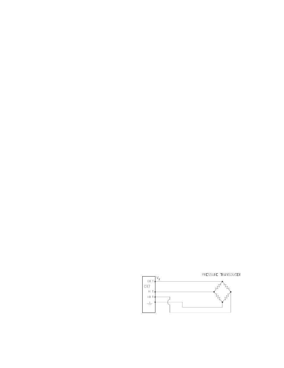
7.14 PRESSURE TRANSDUCER - 4
WIRE FULL BRIDGE
This example describes a measurement made
with a Druck PDCR 10/D depth measurement
pressure transducer. The pressure transducer
was ordered for use with 5 volt positive or
negative excitation (passive temperature
compensation) and has a range of 5 psi or
about 3.5 meters of water. The transducer is
used to measure the depth of water in a stilling
well.
Instruction 6, 4 wire full bridge, is used to
measure the pressure transducer. The high
output of the semiconductor strain gage
necessitates the use of the 50mV input range.
The sensor is calibrated by connecting it to the
CR7 and using Instruction 6 with a multiplier of
1 and an offset of 0, noting the readings (*6
Mode) with 10 cm of water above the sensor
and with 334.6 cm of water above the sensor.
The output of Instruction 6 is 1000 Vs/Vx or
millivolts per volt excitation. At 10 cm the
reading is 0.19963 mV/V and at 334.6 cm the
reading is 6.6485 mV/V. The multiplier to yield
output in cm is:
(334.6 - 10)/(6.6485-.19963) = 50.334 cm/mV/V
The offset is determined after the pressure
transducer is installed in the stilling well. The
sensor is installed 65 cm below the water level
at the time of installation. The depth of water at
this time is determined to be 72.6 cm relative to
the desired reference. When programmed with
the multiplier determined above and an offset of
0, a reading of 65.12 is obtained. The offset for
the actual measurements is thus determined to
be 72.6 - 65.12 = 7.48 cm.
The lead length is approximately 10 feet, so
there is no appreciable error due to lead wire
resistance.
FIGURE 7.14-1. Wiring Diagram for Full
Bridge Pressure Transducer