Campbell Scientific CR7 Measurement and Control System User Manual
Page 141
SECTION 13. CR7 MEASUREMENTS
13-17
-1
0
1
2
3
4
5
6
7
8
9
Excitation
+Vx
-Vx
0 V
Measurement Sequence
Integration
Integration (ms)
Integration
A/D Conversion
A/D Conversion
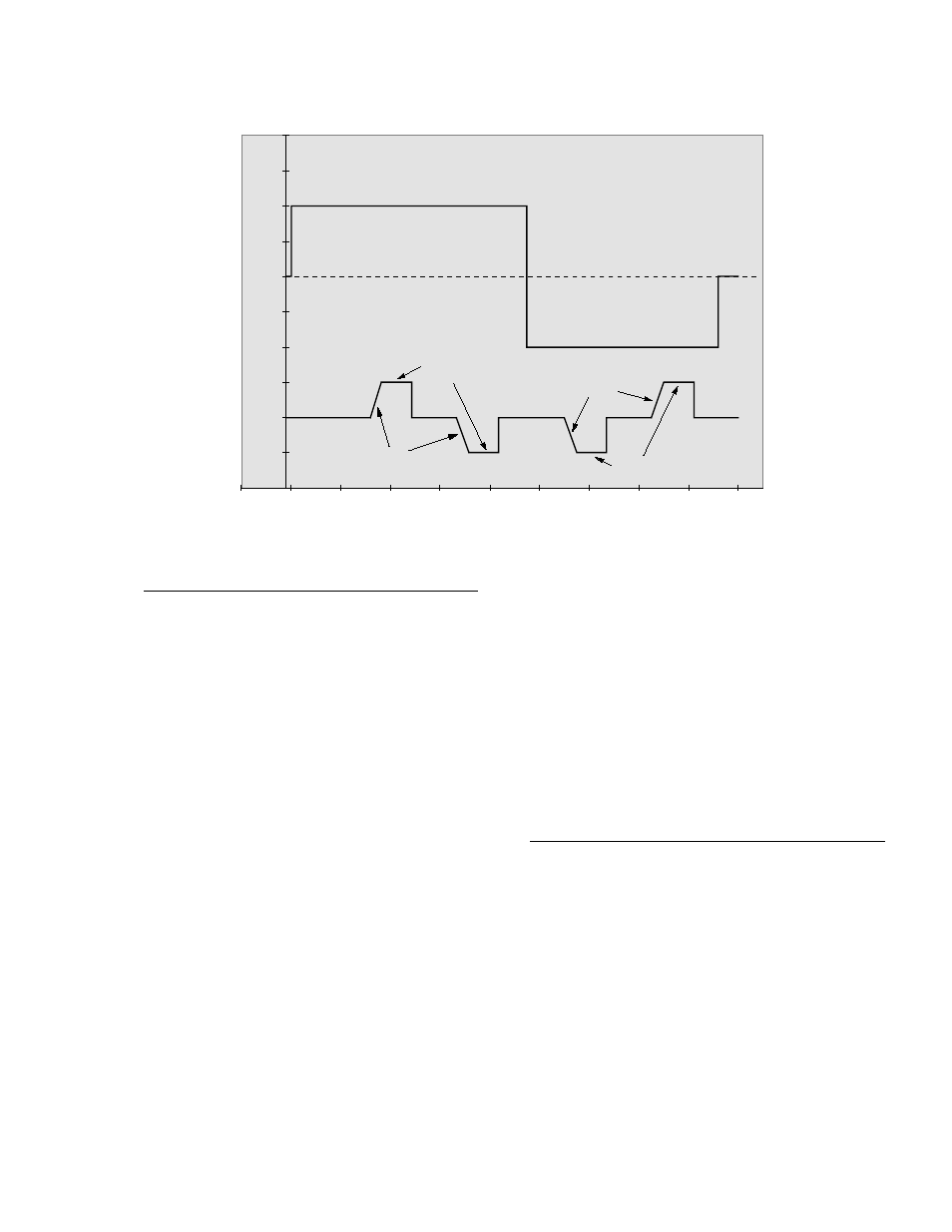
FIGURE 13.5-2. Excitation and Measurement Sequence for 4 Wire Full Bridge
TABLE 13.5-1. Comparison of Bridge
Measurement Instructions
Instr.
Circuit
Description
4
DC Half Bridge
User entered settling
time allows
compensation for
capacitance in long
lead lengths. No
polarity reversal. One
single-ended
measurement.
Measured voltage
output.
5
AC Half Bridge
Rapid reversal of
excitation polarity for
ion depolarization.
One single-ended
measurement at each
excitation polarity.
Ratiometric output.
6
4 Wire
Slightly lower noise than
Full Bridge
9. One differential
measurement at each
excitation polarity.
Ratiometric output.
7
3 Wire
Compensates for lead
Half Bridge
wire resistance,
assuming resistance is
same in both wires.
Two single-ended
measurements at each
excitation polarity.
Ratiometric output.
9
6 Wire
Compensates for lead
Full Bridge
wire resistance. Two
or 4 Wire
differential
Half Bridge
measurements at each
excitation polarity.
Ratiometric output.
Calculating the actual resistance of a sensor
which is one of the legs of a resistive bridge
usually requires the use of one or two
Processing Instructions in addition to the bridge
measurement instruction. Instruction 59 takes a
value, X, in a specified input location and
computes the value MX/(1-X), where M is the
multiplier and stores the result in the original
location. Instruction 42 computes the reciprocal
of a value in an input location. Table 13.5-2 lists
the instructions used to compute the resistance
of any single resistor shown in the diagrams in
Figure 13.5-1, provided the values of the other
resistors in the bridge circuit are known.