12 100 ohm prt in 3 wire half bridge – Campbell Scientific CR7 Measurement and Control System User Manual
Page 76
SECTION 7. MEASUREMENT PROGRAMMING EXAMPLES
7-8
a multiplier of 1. The PRT is then placed in an
ice bath (0 oC; Rs=R0), and the result of the
bridge measurement is read using the *6 Mode.
The reading is Rs/Rf, which is equal to R0/Rf
since Rs = R0, the correct value of the
multiplier, Rf/R0, is the reciprocal of this
reading. The initial reading assumed for this
example was 0.9890, the correct multiplier is:
Rf/R0 = 1/0.9890 = 1.0111.
The fixed 100 ohm resistor must be thermally
stable. Its precision is not important because
the exact resistance is incorporated, along with
that of the PRT, into the calibrated multiplier.
The 10 ppm/oC temperature coefficient of the
fixed resistor will limit the error due to its change
in resistance with temperature to less than 0.15
oC over the specified temperature range.
Because the measurement is ratiometric
(Rs/Rf), the properties of the 10 kohm resistor
do not affect the result.
PROGRAM
01:
P9
Full BR w/Compensation
01:
1
Rep
02:
4
50 mV slow EX Range
03:
4
50 mV slow BR Range
04:
1
IN Card
05:
1
IN Chan
06:
1
EX Card
07:
1
EX Chan
08:
1
Meas/EX
09: 4200
mV Excitation
10:
1
Loc [:Rs/Ro ]
11:
1.0111
Mult
12:
0
Offset
02:
P16
Temperature RTD
01:
1
Rep
02:
1
R/Ro Loc Rs/Ro
03:
2
Loc [:TEMP degC]
04:
1
Mult
05:
0
Offset
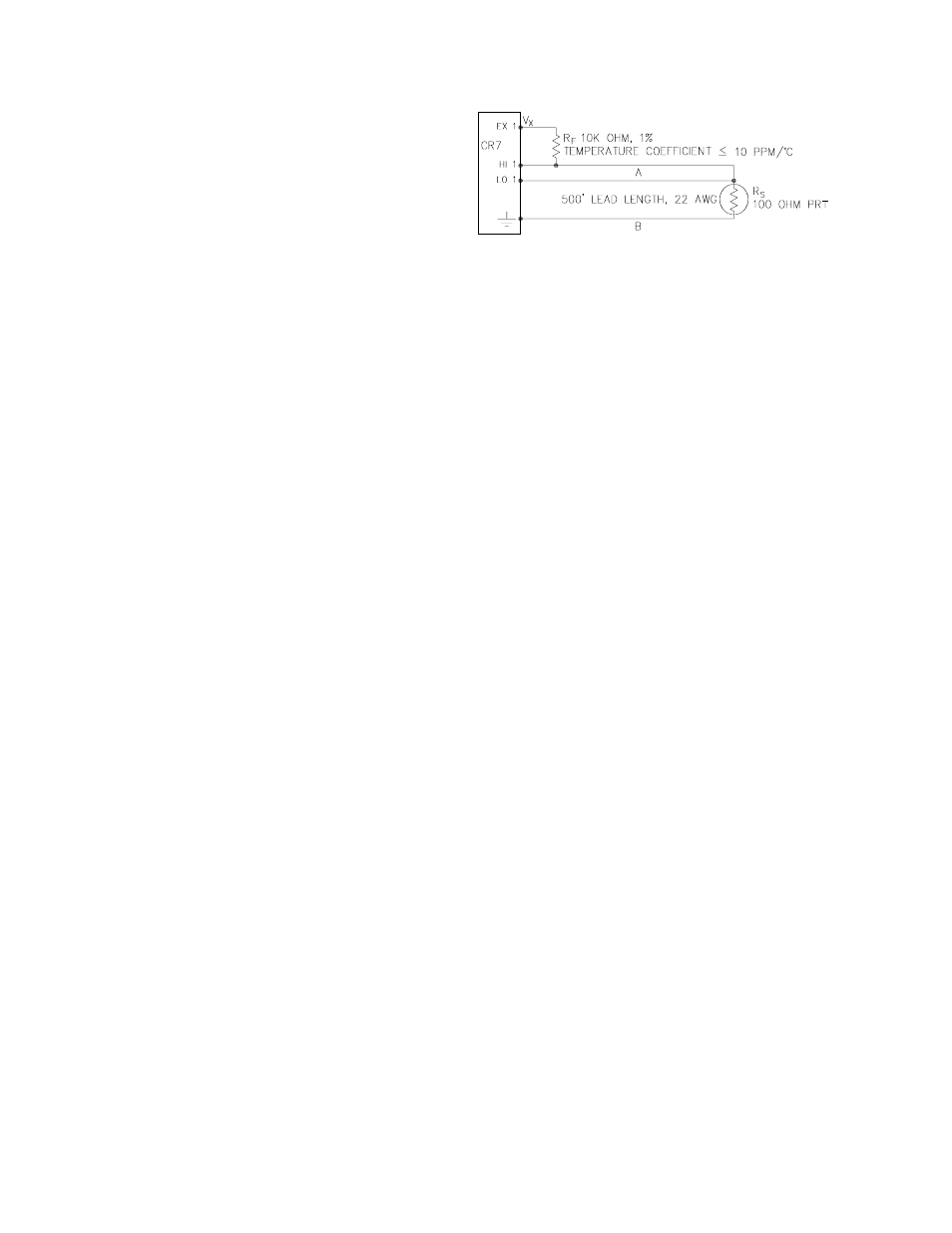
7.12 100 OHM PRT IN 3 WIRE HALF
BRIDGE
The temperature measurement requirements in
this example are the same as in section 7.11.
In this case a three wire half bridge, Instruction
7, is used to measure the resistance of the
PRT. The diagram of the PRT circuit is shown
in Figure 7.12-1.
Figure 7.12-1. 3 Wire Half-Bridge Used to
Measure 100 ohm PRT
As in the example in section 7.11, the excitation
voltage is calculated to be the maximum
possible yet allow the ±50 mV measurement
range. The 10 kohm resistor has a tolerance of
±1%, thus, the lowest resistance to expect from
it is 9.9 kohms. We calculate the maximum
excitation voltage (Vx) to keep the voltage drop
across the PRT less than 50 mV:
0.050V > Vx 115.54/(9900+115.54); Vx < 4.33V
The excitation voltage used is 4.3V.
The multiplier used in Instruction 7 is
determined in the same manner as in section
7.11. In this example the multiplier (Rf/R0) is
assumed to be 100.93.
The 3 wire half bridge compensates for lead
wire resistance by assuming that the resistance
of wire A is the same as the resistance of wire
B. The maximum difference expected in wire
resistance is 2%, but is more likely to be on the
order of 1%. The resistance of Rs calculated
with Instruction 7, is actually Rs plus the
difference in resistance of wires A and B. The
average resistance of 22 AWG wire is 16.5
ohms per 1000 feet, which would give each 500
foot lead wire a nominal resistance of 8.3 ohms.
Two percent of 8.3 ohms is 0.17 ohms.
Assuming that the greater resistance is in wire
B, the resistance measured for the PRT (R0 =
100 ohms) in the ice bath would be 100.17
ohms, and the resistance at 40 oC would be
115.71. The measured ratio Rs/R0 is 1.1551,
the actual ratio is 115.54/100 = 1.1554. The
temperature computed by Instruction 17 from
the measured ratio would be about 0.1 oC lower
than the actual temperature of the PRT. This
source of error does not exist in the example in
section 7.11, where the 4 wire half bridge is
used to measure PRT resistance.