Section 6. cs i/o 9 pin serial input/output, 1 pin description, Cs i/o – Campbell Scientific CR7 Measurement and Control System User Manual
Page 63
6-1
SECTION 6. CS I/O 9 PIN SERIAL INPUT/OUTPUT
6.1 PIN DESCRIPTION
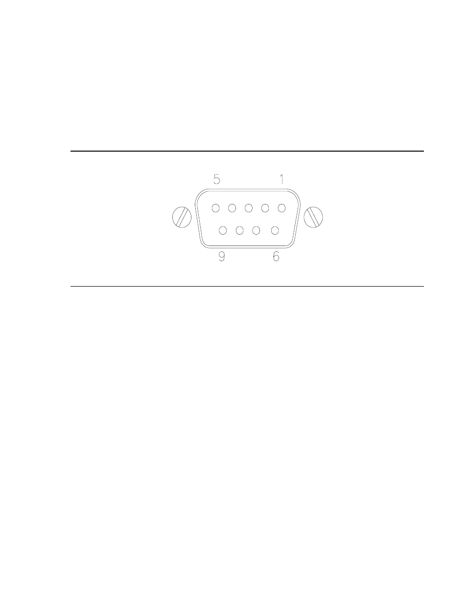
All external communication peripherals connect
to the CR7 through the 9-pin CS I/O connector
(Figure 6.1-1). Table 6.1-1 gives a brief
description of each pin's function.
CS I/O
FIGURE 6.1-1. CS I/O 9 Pin Connection
TABLE 6.1-1. Pin Description
ABR =
Abbreviation for the function name.
PIN
=
Pin number.
O
=
Signal Out of the CR7 to a peripheral.
I
=
Signal Into the CR7 from a peripheral.
PIN
ABR
I/O
Description
1
5V
O
5V: Sources 5V DC, used
to power some peripherals.
2
G
Ground: Provides a power
return for pin 1 (5V), and is
used as a reference for
voltage levels.
3
RING
I
Ring: When raised by a
peripheral the CR7 enters
telecommunications.
4
RXD
I
Receive Data: Serial data
transmitted by a peripheral
are received on pin 4.
5
ME
O
Modem Enable: Raised by
the CR7 after the ring line
has been raised.
PIN
ABR
I/O
Description
6
PE
O
Printer Enable: Raised to
enable Storage Module or
other print device.
7
G
I/O
Ground, common with pin 2.
8
12 V
O
12 volt power for
peripherals.
9
TXD
O
Transmit Data: Serial data
are transmitted from the
CR7 to peripherals on pin
9; logic low marking (0V)
logic high spacing (5V)
standard asynchronous
ASCII, 8 data bits, no
parity, 1 start bit, 1 stop bit,
300, 1200, 9600, 76,800
baud (user selectable).