2 effect of lead length on signal rise time – Campbell Scientific CR7 Measurement and Control System User Manual
Page 129
SECTION 13. CR7 MEASUREMENTS
13-5
TABLE 13.3-2. Properties of Three Belden Lead Wires Used by Campbell Scientific
Belden
R
l
C
w
Wire #
Conductors
Insulation
AWG
(ohms/1000ft.)
(pfd/ft.)
8641
1 shld. pair
polyethylene
24
23
42
8771
1 shld. 3 cond.
polyethylene
22
15
41
8723
2 shld. pair
polypropylene
22
15
62
FIGURE 13.3-4. Wire Manufacturers
Capacitance Specifications, Cw
DIELECTRIC ABSORPTION
The dielectric absorption of insulation
surrounding individual conductors can seriously
effect the settling waveform by increasing the
time required to settle as compared to a simple
exponential. Dielectric absorption is difficult to
quantify but it can have a serious effect on low
level measurements, for example 50mV or less.
The primary rule to follow in minimizing
dielectric absorption is: AVOID PVC
INSULATION around conductors. PVC cable
jackets are permissible since the jackets don't
contribute to the lead capacitance because the
jacket is outside the shield. Campbell Scientific
uses only polyethylene and polypropylene
insulated conductors in CR7 sensors (see Table
13.3-2) since these materials have negligible
dielectric absorption. Teflon insulation is also
very good but quite expensive.
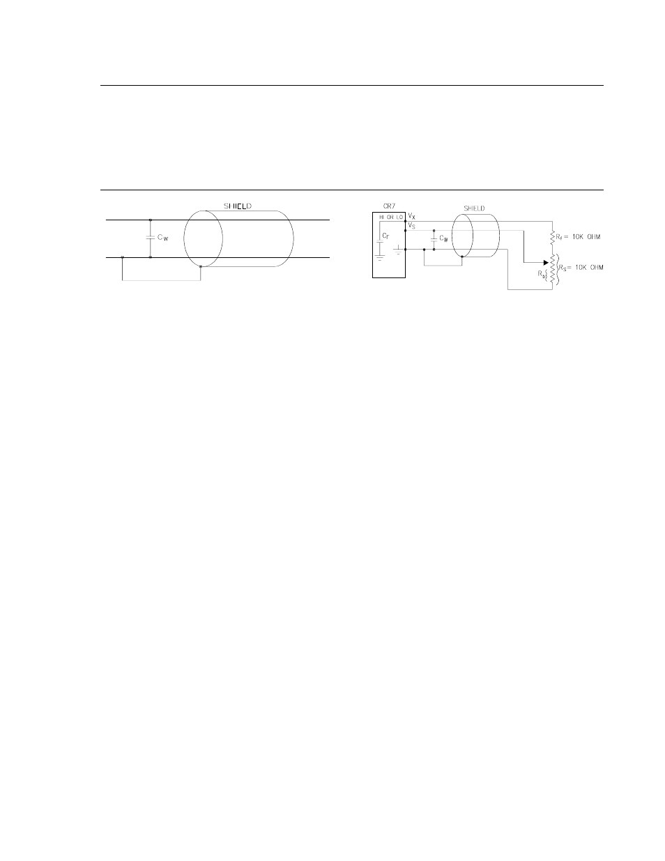
13.3.2 EFFECT OF LEAD LENGTH ON SIGNAL
RISE TIME
In the 024A Windvane, a potentiometer sensor,
the peak transient voltage is much less than the
true signal voltage (Table 13.3-5). This means
the signal rise time is the major source of error
and the time constant is the same as if Cw were
between the signal lead and ground as
represented below.
FIGURE 13.3-5. Model 024A Wind Direction
Sensor
Ro, the source resistance, is not constant
because Rb varies from 0 to 10 kohms over the
0 to 360 degree wind direction range. The
source resistance is given by:
Ro = Rb(Rs-Rb+Rf)/(Rs+Rf) = Rb(20k-Rb)/20k
[13.3-12]
Note that at 360o, Ro is at a maximum of 5k
(Rb=10k) and at 0o, Ro is 0 (Rb=0). It follows
that settling errors are less at lower direction
values.
The value of Rb for any direction D (degrees) is
given by:
Rb(kohms) = (10k)(D)/360
[13.3-13]
Equation 13.3-6 can be rewritten to yield the
settling error of a rising signal directly in units of
degrees.
Error (degrees)
=
−
+
De
t
C
C L
o
f
w
/(R (
))
[13.3-14]
Equation 13.3-12, -13 and -14 can be combined
to estimate the error directly in degrees at
various directions and lead lengths (Table 13.3-
3). Constants used in the calculations are given
below:
Cf = 0.01 ufd
Cw = 41 pfd/ft, Belden #8771 wire
t = 0.5 ms