3 transients induced by switched excitation – Campbell Scientific CR7 Measurement and Control System User Manual
Page 130
SECTION 13. CR7 MEASUREMENTS
13-6
TABLE 13.3-3. Settling Error (Degrees) for
024A Wind Direction Sensor vs. Lead Length
Wind
- - - - - Error - - - - -
Direction
L=1000 ft.
L=500 ft.
360o
47o
8o
270o
31o
5o
180o
12o
1o
90o
1o
0o
The values in Table 13.3-3 show that significant
error occurs at large direction values for leads
in excess of 250 feet. Instruction 4, Excite,
Delay and Measure should be used to eliminate
errors in these types of situations. Using a
10ms delay, settling errors are eliminated up to
lengths that exceed the drive capability of the
excitation channel (
≈2000 ft.).
13.3.3 TRANSIENTS INDUCED BY SWITCHED
EXCITATION
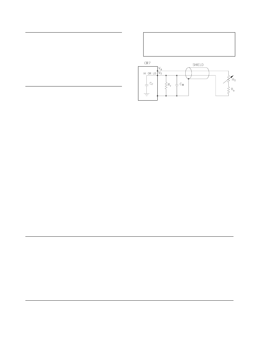
Figure 13.3-6 shows a typical half-bridge,
resistive sensor such as Campbell Scientific's
Model 107 Temperature probe, connected to
the CR7. The leadwire is a single shielded pair,
used for conducting the excitation, Vx and
signal, Vs voltages. When Vx is switched on, a
transient is capacitively induced in Vs, the signal
voltage. If the peak transient level, Veo, is less
than the true signal, Vso, the transient has no
effect on the measurement but if Veo is greater
than Vso it must settle to the correct signal
voltage to avoid errors.
NOTE:
Excitation transients are eliminated
if an option exists to contain excitation leads
in a shield independent from the signal
leads.
FIGURE 13.3-6. Resistive Half-Bridge
Connected to Single-Ended CR7 Input
The size of the peak transient is linearly related
to the excitation voltage and increases as the
bridge resistor, Rf, increases. Table 13.3-4
shows measured levels of Veo for 1000 foot
lengths of three Belden wires used in Campbell
Scientific sensors. Values are given for Rf
equal 1 kohm and 10 kohm. Table 13.3-4 is
meant only to provide estimates of the size of
excitation transients encountered since the
exact level will depend upon the specific sensor
configuration.
Equation 13.3-7 can be solved for the maximum
lead length, L, permitted to maintain a specified
error limit. Combining Equations 7 and 4 and
solving for L gives:
L = -(RoCf + (t/ln(Ve/Veo)))/RoCw
[13.3-15]
where Ve is the measurement error limit.
TABLE 13.3-4. Measured Peak Excitation Transients for 1000 Foot Lengths of Three Belden Lead
Wires Used by Campbell Scientific
- - - - - - - - - - - Veo(mV) - - - - - - - - -
Vx(mV)
Rf=1 kohm
Rf=10 kohm
#
#
#
#
#
#
8641
8771
8723
8641
8771
8723
5000
125
200
130
215
320
180
4000
100
165
110
180
260
150
3000
75
130
90
140
200
110
2000
50
100
60
100
140
80
1000
25
65
40
60
90
40