5 bridge resistance measurements – Campbell Scientific CR7 Measurement and Control System User Manual
Page 139
SECTION 13. CR7 MEASUREMENTS
13-15
is 100 oC and the upper limit of the extension
grade wire is 200 oC. With the other types of
thermocouples the reference compensation
range equals or is greater than the extension
wire range. In any case, errors can arise if
temperature gradients exist within the junction
box.
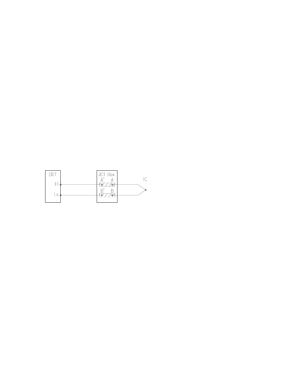
Figure 13.4-1 illustrates a typical junction box.
Terminal strips will be a different metal than the
thermocouple wire. Thus, if a temperature
gradient exists between A and A' or B and B',
the junction box will act as another
thermocouple in series, creating an error in the
voltage measured by the CR7. This
thermoelectric offset voltage is a factor whether
or not the junction box is used for the reference.
it can be minimized by making the thermal
conduction between the two points large and
the distance small. The best solution in the
case where extension grade wire is being
connected to thermocouple wire would be to
use connectors which clamped the two wires in
contact with each other.
Figure 13.4-1. Diagram of Junction Box
An external reference junction box must be
constructed so that the entire terminal area is
very close to the same temperature. This is
necessary so that a valid reference temperature
can be measured and to avoid a thermoelectric
offset voltage which will be induced if the
terminals at which the thermocouple leads are
connected (points A and B in Figure 13.4-2) are
at different temperatures. The box should
contain elements of high thermal conductivity,
which will act to rapidly equilibrate any thermal
gradients to which the box is subjected. It is not
necessary to design a constant temperature
box, it is desirable that the box respond slowly
to external temperature fluctuations.
Radiation shielding must be provided when a
junction box is installed in the field. Care must
also be taken that a thermal gradient is not
induced by conduction through the incoming
wires. The CR7 can be used to measure the
temperature gradients within the junction box.
13.5 BRIDGE RESISTANCE
MEASUREMENTS
There are five bridge measurement instructions
included in the standard CR7 software. Figure
13.5-1 shows the circuits that would typically be
measured with these instructions. In the
diagrams, the resistors labeled Rs would
normally be the sensors and those labeled Rf
would normally be fixed resistors. Circuits other
than those diagrammed could be measured,
provided the excitation and type of
measurements were appropriate.
With the exception of Instruction 4, which
applies an excitation voltage then waits a
specified time before making a single ended
measurement, all of the bridge measurements
make one set of measurements with the
excitation as programmed and another set of
measurements with the excitation polarity
reversed. The error in the two measurements
due to thermal emfs can then be accounted for
in the processing of the measurement
instruction. In Instructions 6-9 the excitation
channel maintains the excitation voltage until
after the analog to digital conversion is
completed. In Instruction 5, the AC half bridge
grounds the excitation channel as soon as the
integration portion of the measurement is
completed. Figure 13.5-2 shows the excitation
and measurement sequence for Instruction 6, a
4 wire full bridge. When more than one
measurement per sensor is necessary
(Instructions 7 and 9), excitation is applied
separately for each measurement (e.g., in
Instruction 9 used for a 4 wire half bridge, the
differential measurement of the voltage drop
across the sensor is made with the excitation at
both polarities and then excitation is again
applied and reversed for the single ended
measurement of the voltage drop across the
fixed resistor.