Campbell Scientific CR7 Measurement and Control System User Manual
Page 128
SECTION 13. CR7 MEASUREMENTS
13-4
Since the peak transient, Veo, causes
significant error only if it is several times larger
than the signal, Vso, error calculations made in
this section approximate Ve'o by Veo, i.e., Veo
≈ Veo-Vso.
If the input settling time constant,
τ , is known, a
quick estimation of the settling error as a
percentage of the maximum error (Vso for
rising, V'eo for decaying) is obtained by knowing
how many time constants (t/
τ) are contained in
the 0.5 ms CR7 input settling interval (t). The
familiar exponential decay relationship is given
in Table 13.3-1 for reference.
TABLE 13.3-1. Exponential Decay, Percent
of Maximum Error vs. Time in Units of
τ
Time
%
Time
%
Constants Max. Error Constants
Max. Error
0
100.0
5
0.7
1
36.8
7
0.1
3
5.0
10
0.004
Before proceeding with examples of the effect
of long lead lengths on the measurement, a
discussion on obtaining the source resistance,
Ro, and lead capacitance, CwL, is necessary.
DETERMINING SOURCE RESISTANCE
The source resistance used to estimate the
settling time constant is the resistance the CR7
input "sees" looking out at the sensor. For our
purposes the source resistance can be defined
as the resistance from the CR7 input through all
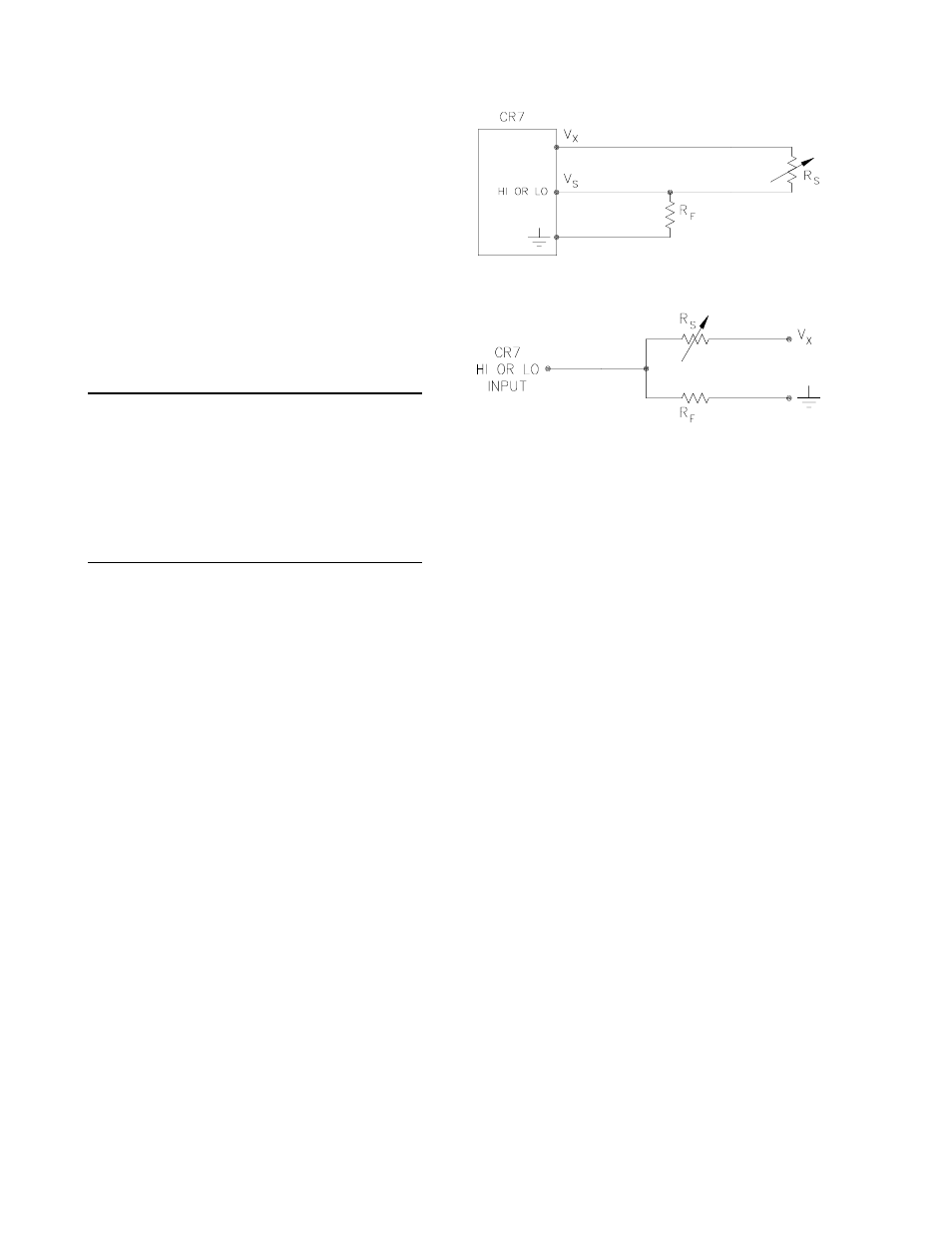
external paths back to the CR7. Figure 13.3-2
shows a typical resistive sensor, (e.g., a
thermistor) configured as a half-bridge. Figure
13.3-3 shows Figure 13.3-2 redrawn in terms of
the resistive paths determining the source
resistance Ro, is given by the parallel
resistance of Rs and Rf, as shown in Equation
13.3-8.
FIGURE 13.3-2. Typical Resistive Half-Bridge
FIGURE 13.3-3. Source Resistance Model
for Half-Bridge Connected to the CR7
Ro = RsRf/(Rs+Rf)
[13.3-8]
If Rf is much smaller, equal to or much greater
than Rs, the source resistance can be
approximated by Equations 13.3-9 through
13.3-11, respectively.
Ro ≈ Rf, Rf< [13.3-9] Ro = Rf/2, Rf=Rs [13.3-10] Ro ≈ Rs, Rf>>Rs [13.3-11] The source resistance for several Campbell DETERMINING LEAD CAPACITANCE Wire manufacturers typically provide two measurements such as Figure 13.3-2, the pfd/ft. Cw is actually the sum of capacitance between the two conductors and the
Scientific sensors are given in column 3 of
Table 13.3-5.
capacitance specifications 1) the capacitance
between the two leads with the shield floating
and 2) the capacitance between the two leads
with the shield tied to one lead. Since the input
lead and the shield are tied to ground (often
through a bridge resistor, Rf) in single ended
second specification is used in determining lead
capacitance. Figure 13.3-4 is a representation
of this capacitance, Cw, usually specified as
capacitance between the top conductor and the
shield. Capacitance for 3 Belden leadwires
used in Campbell Scientific sensors is shown in
column 6 of Table 13.3-2.