8. wiring of power and communications, 1. sdm wiring – Campbell Scientific CPEC200 Closed-Path Eddy-Covariance System User Manual
Page 35
CPEC200 Closed-Path Eddy-Covariance System
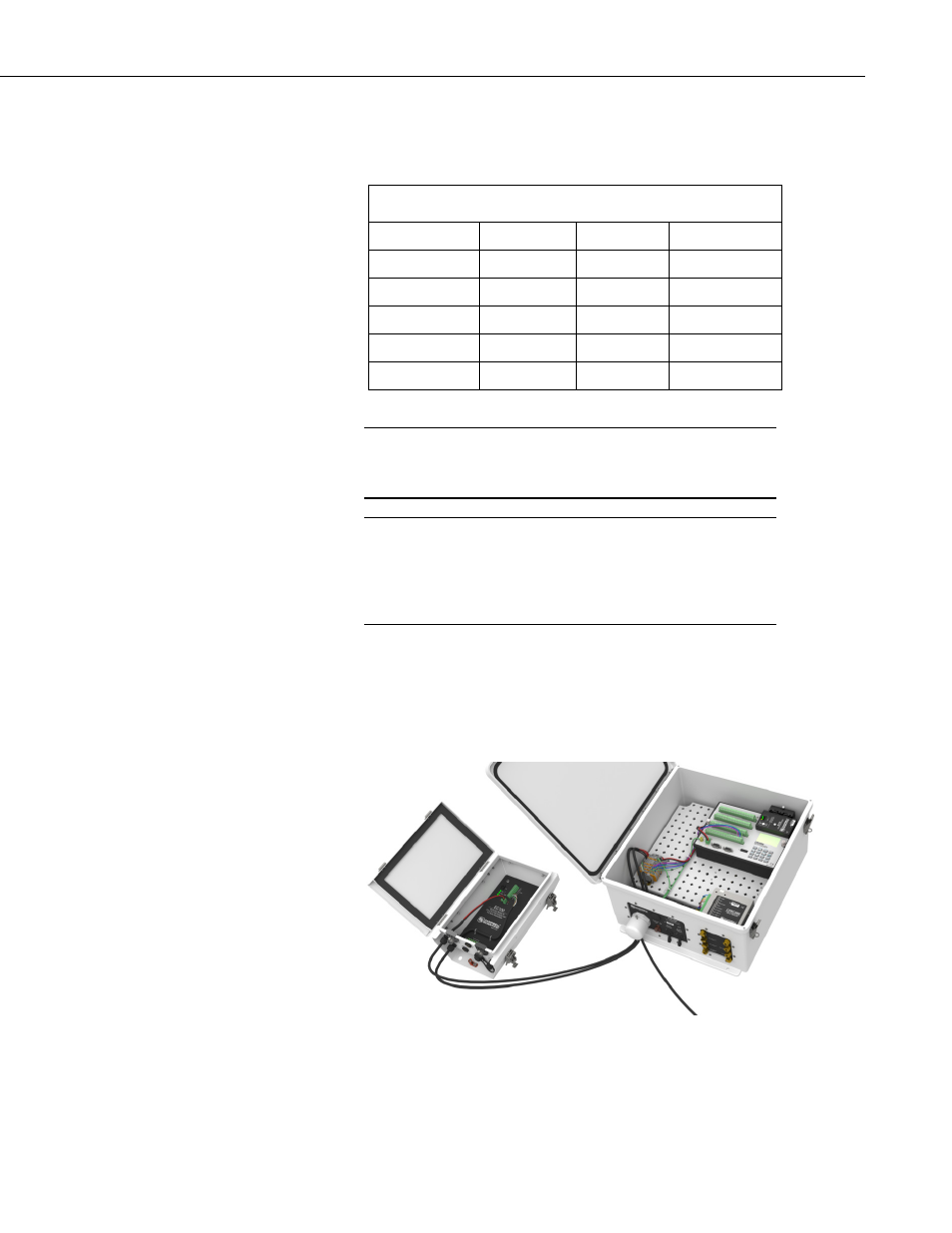
Wire the SDM communications cable (CABLE4CBL-L) between the EC100
and the CPEC200 enclosure as shown in FIGURE 5-8, FIGURE 5-9, and
FIGURE 5-10. TABLE 5-1 shows the color scheme of the SDM wires.
TABLE 5-1. SDM Wiring
Description
Wire Color
EC100
CPEC200
SDM Data
Green
SDM-C1
SDM-C1
SDM Clock
White
SDM-C2
SDM-C2
SDM Enable
Red
SDM-C3
SDM-C3
Digital Ground
Black
Ground
Ground
Shield
Clear
Ground
Ground
To bring cables into the CPEC200 enclosure, remove the cap from
the cable feedthrough by loosening the thumbscrew and twisting
the cap while pulling it off.
To connect a wire to the DIN rail terminal blocks of the CPEC200
enclosure, insert a small screwdriver into the square hole to open
the spring-loaded contacts. Insert the wire into the corresponding
round hole and then remove the screwdriver. Gently tug the wire
to confirm it is secure.
Ensure the CPEC200 enclosure is not powered, and wire the power cable
(CABLEPCBL-L) from the EC100 electronics to the CPEC200 enclosure as
shown in FIGURE 5-8, FIGURE 5-9, and FIGURE 5-10.
Secure the SDM and power cables in the EC100 with a cable tie.
FIGURE 5-8. Wiring of power and communications
NOTE
NOTE
25