Paxc - 1/8 din c, Paxr - 1/8 din r, Odel – Red Lion PAXR User Manual
Page 4: Ounter, Eter, Paxr specifications, Paxc specifications
4
m
Odel
paXC - 1/8 din C
OunTer
ANNUNCIATORS:
A - Counter A
B - Counter B
C - Counter C
- Upper significant digit display of counter
SP1 - setpoint 1 output state
SP2 - setpoint 2 output state
SP3 - setpoint 3 output state
SP4 - setpoint 4 output state
COUNTER DISPLAYS:
Maximum display: 8 digits: ± 99999999 (greater than 6 digits, display
alternates between high order and low order.)
INPUTS A and B:
DIP switch selectable to accept pulses from a variety of sources including
switch contacts, TTL outputs, magnetic pickups and all standard RLC
sensors.
LOGIC: Input trigger levels V
IL
= 1.5 V max.; V
IH
= 3.75 V min.
Current sinking: Internal 7.8 KΩ pull-up to +12 VDC, I
MAX
= 1.9 mA.
Current sourcing: Internal 3.9 KΩ pull-down, 7.3 mA max. @ 28 VDC,
V
MAX
= 30 VDC.
Filter: Damping capacitor provided for switch contact bounce. Limits
input frequency to 50 Hz and input pulse widths to 10 msec. minimum.
DUAL COUNT MODES:
When any dual count mode is used, then User Inputs 1 and/or 2 will
accept the second signal of each signal pair. The user inputs do not have
the Logic/Mag, HI/LO Freq, and Sink/Source input setup switches. The
user inputs are inherently a logic input with no low frequency filtering.
Any mechanical contacts used for these inputs in a dual count mode
must be debounced externally. The user input may only be selected for
sink/source by the User Jumper placement.
m
Odel
paXr - 1/8 din r
aTe
m
eTer
PAXR SPECIFICATIONS
ANNUNCIATORS:
- Rate
- Maximum (High) Rate
- Minimum (Low) Rate
SP1 - setpoint 1 output state
SP2 - setpoint 2 output state
SP3 - setpoint 3 output state
SP4 - setpoint 4 output state
RATE DISPLAY:
Accuracy: ±0.01%
Minimum Frequency: 0.01 Hz
Maximum Frequency: 34 KHz
Maximum Display: 5 Digits: 99999
Adjustable Display (low) Update: 0.1 to 99.9 seconds
Over Range Display: “
”
INPUT A:
DIP switch selectable to accept pulses from a variety of sources including
TTL outputs, magnetic pickups and all standard RLC sensors.
LOGIC: Input trigger levels V
IL
= 1.5 V max.; V
IH
= 3.75 V min.
Current sinking: Internal 7.8 KΩ pull-up to +12 VDC, I
MAX
= 1.9 mA.
Current sourcing: Internal 3.9 KΩ pull-down, 7.3 mA max. @ 28 VDC,
V
MAX
= 30 VDC.
MAGNETIC PICKUP:
Sensitivity: 200 mV peak
Hysteresis: 100 mV
Input impedance: 3.9 KΩ @ 60 Hz
Maximum input voltage: ±40 V peak, 30 Vrms
6-DIGIT LED DISPLAY (Alternating 8 digits for counting)
DUAL COUNT QUAD INPUTS
UP TO 3 COUNT DISPLAYS
SETPOINT ALARM OUTPUTS (W/Plug-in card)
5-DIGIT LED DISPLAY
RATE INDICATION
MINIMUM/MAXIMUM RATE DISPLAYS
SETPOINT ALARM OUTPUTS (W/Plug-in card)
PAXC SPECIFICATIONS
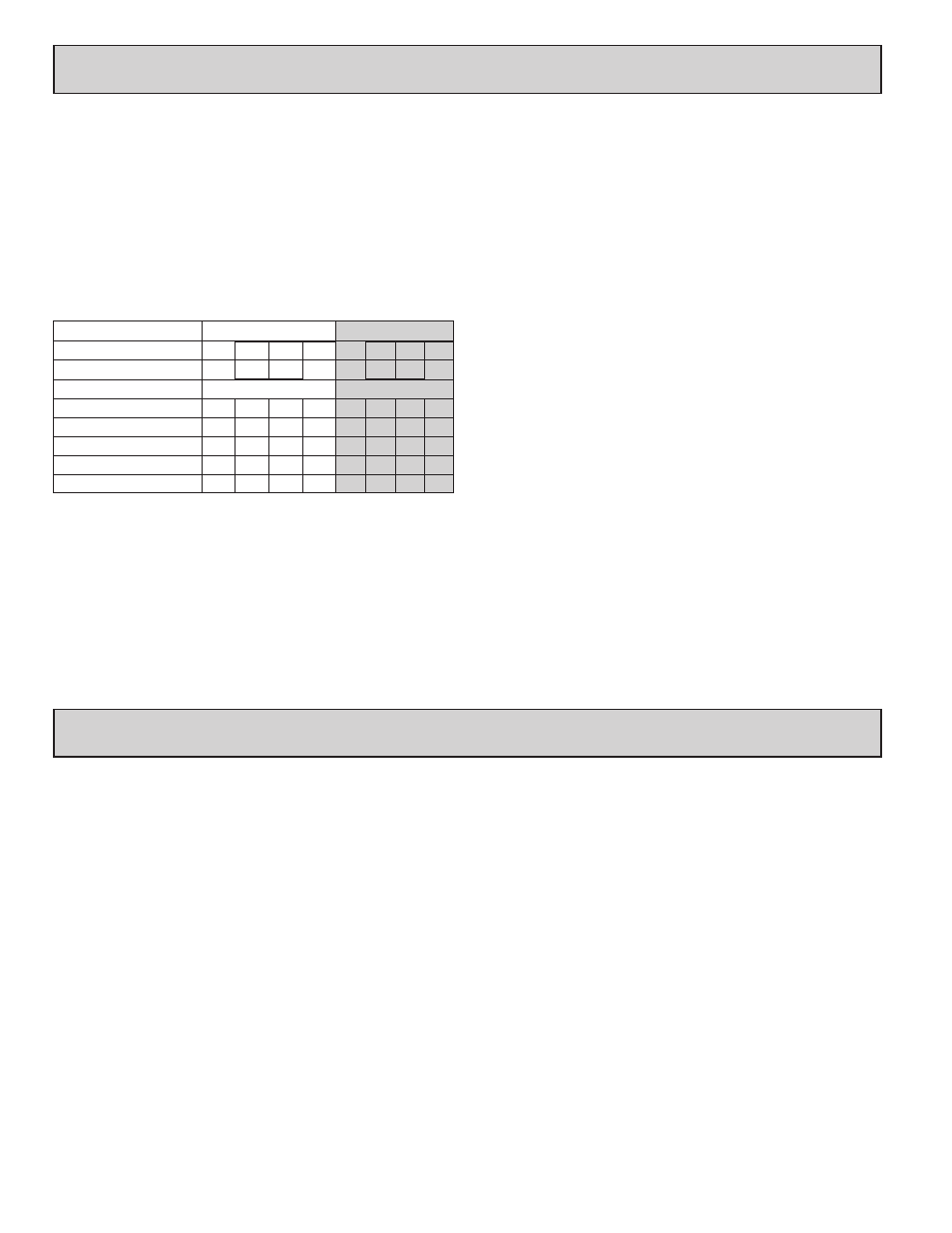
MAXIMUM SIGNAL FREQUENCIES:
To determine the maximum frequency for the input(s), first answer the
questions with a yes (Y) or no (N). Next determine the Count Mode to be
used for the counter(s). If dual counters are used with different Count Modes,
then the lowest frequency applies to both counters.
Notes:
1. Counter Modes are explained in the Module 1 programming section.
2. Listed values are with frequency DIP switch set on HI frequency.
FUNCTION QUESTIONS
Dual: Counter A & B
Single: Counter A or B
Are any setpoints used?
N
N
Y
Y
N
N
Y
Y
Is Counter C used?
N
Y
N
Y
N
Y
N
Y
COUNT MODE
(Values are in KHz)
(Values are in KHz)
Count x1
34
25
18
15
13 12
9
7.5
Count x2
17
13
9
7
9
7
5
4
Quadrature x1
22
19
12
10
7
6
4
3.5
Quadrature x2
17
13
9
7
7
6
4
3.5
Quadrature x4
8
6
4
3