Red Lion PAXR User Manual
Page 13
13
13
COUNTER B OPERATING MODE
Select the operating mode for Counter B.
SELECTION
MODE
DESCRIPTION
Does not count.
Count X1
Adds Input B falling edge.
Count X1
w/direction
Adds Input B falling edge if User 2 is high. Subtracts
Input B falling edge if User 2 is low.
Quad X1
Adds Input B rising edge when User 2 is high.
Subtracts Input B falling edge when User 2 is high.
Quad X2
Adds Input B rising edge when User 2 is high and
Input B falling edge when User 2 is low. Subtracts
Input B falling edge when User 2 is high and Input B
rising edge when User 2 is low.
Count X2
Adds Input B rising and falling edges.
Count X2
w/direction
Adds Input B rising and falling edges if User 2 is
high. Subtracts Input B rising and falling edge if User
2 is low.
COUNTER B RESET ACTION
When Counter B is reset, it returns to zero or Counter B count load value.
This reset action affects all Counter B resets, except the Setpoint Counter Auto
Reset Action in Module 6.
COUNTER B DECIMAL POSITION
This selects the decimal point position for Counter B and any setpoint value
assigned to Counter B. The selection will also affect Counter B scale factor
calculations.
COUNTER B SCALE FACTOR
The number of input counts is multiplied by the scale factor and the scale
multiplier to obtain the desired process value. A scale factor of 1.00000 will
result in the display of the actual number of input counts. (Details on scaling
calculations are explained at the end of this section.)
to
COUNTER B SCALE MULTIPLIER
The number of input counts is multiplied by the scale multiplier and the scale
factor to obtain the desired process value. A scale multiplier of 1 will result in
only the scale factor affecting the display. (Details on scaling calculations are
explained at the end of this section.)
COUNTER B COUNT LOAD VALUE
When reset to count load action is selected, Counter B will reset to this value.
to
SCALING CALCULATIONS
Each counter has the ability to scale an input signal to a desired display
value. This is accomplished by the counter mode (x-
), scale factor (x
),
scale multiplier (x
) and decimal point (x
). The scale factor is
calculated using:
SF (x
) = Desired Display Decimal DDD
(Number of pulses per ‘single’ unit x CM x SM)
Where:
Desired
Display
Decimal DDD
x
Counter Decimal Selection
1
0
None
10
0.0
Tenths
100
0.00
Hundredths
1000
0.000
Thousandths
10000
0.0000
Ten Thousandths
100000
0.00000
Hundred Thousandths
Number of pulses per ‘single’ unit: pulses per unit generated by the
process (i.e. # of pulses per foot)
CM: Counter Mode(x-
) times factor of the mode 1,2 or 4.
SM: Scale Multiplier (x
) selection of 1, 0.1 or 0.01.
Example:
1. Show feet to the hundredths (0.00) with 100 pulses per foot:
Scale Factor would be 100 / (100 x 1 x 1) = 1
(In this case, the scale multiplier and counter mode factor are 1)
2. Show feet with 120 pulses per foot: Scale Factor would be 1 / (120 x 1 x 1)
= 0.0083333. (In this case, the scale multiplier of 0.01 could be used: 1 / (120
x 1 x 0.01) = 0.83333 or show to hundredths (0.00): 100 / (120 x 1 x 1) =
0.8333.)
General Rules on Scaling
1. It is recommended that, the scale factor be as close as possible to, but not
exceeding 1.00000. This can be accomplished by increasing or decreasing
the counter decimal point position, using the scale multiplier, or selecting a
different count mode.
2. To double the number of pulses per unit, use counter modes direction X2 or
quad X2. To increase it by four times, use counter mode quad X4. Using
these modes will decrease the maximum input frequency.
3. A scale factor greater than 1.00000 will cause Counter display rounding. In
this case, digit jumps could be caused by the internal count register rounding
the display. The precision of a counter application cannot be improved by
using a scale factor greater than 1. 00000.
4. The number of pulses per single unit must be greater than or equal to the
DDD value for the scale factor to be less than or equal to one.
5. Lowering the scale factor can be accomplished by lowering the counter
decimal position. (Example: 100 (Hundredths)/10 pulses = 10.000 lowering
to 10 (Tenths)/10 = 1.000.)
COUNTER B RESET POWER-UP
Counter B may be programmed to reset at each meter power-up.
8 DIGIT COUNT VALUES
Any counter display value below -99999 or above 999999 (less decimal
point) will consist of a two part display. This display alternates between the
least 6 significant digits and the remaining most significant digits beginning
with “
” in the display. If the display exceeds ± 99999999 the display will roll
to zero and continue counting. Outputs cannot be set to counter values above 6
digits. The annunciator, indicating the counter being displayed, will flash when
the value is above 6 digits.
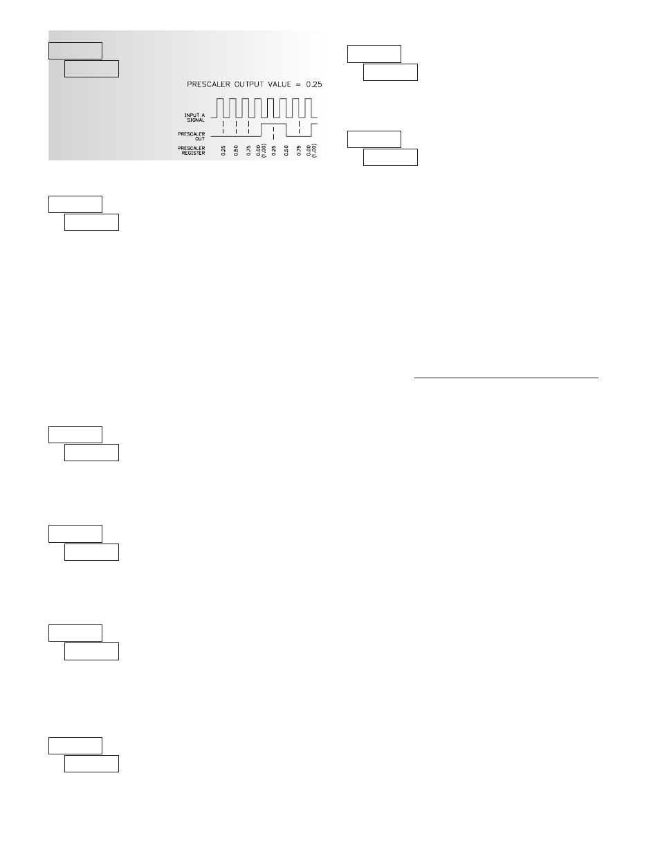
PAXI: PRESCALER SCALE VALUE
to
The prescaler output frequency
is the Input A frequency times the
prescaler scale value.