1 module 1 - c, A & b i, Paxc & i – Red Lion PAXR User Manual
Page 12: Ount, Nput, Arameters
PAXI: PRESCALER OUTPUT ENABLE
12
COUNTER A OPERATING MODE
Select the operating mode for Counter A.
SELECTION
MODE
DESCRIPTION
Does not count.
Count X1
Adds Input A falling edge.
Count X1
w/direction
Adds Input A falling edge if Input B is high. Subtracts
Input A falling edge if Input B is low.
Count X1
w/direction
Adds Input A falling edge if User 1 is high. Subtracts
Input A falling edge if User 1 is low.
Quad X1
Adds Input A rising edge when Input B is high.
Subtracts Input A falling edge when Input B is high.
Quad X2
Adds Input A rising edge when Input B is high and
Input A falling edge when Input B is low. Subtracts
Input A falling edge when Input B is high and Input A
rising edge when Input B is low.
Quad X4
Adds Input A rising edge when Input B is high, Input
A falling edge when Input B is low, Input B rising
edge when Input A is low, and Input B falling edge
when Input A is high. Subtracts Input A falling edge
when Input B is high, Input A rising edge when Input
B is low, Input B rising edge when Input A is high,
and Input B falling edge when Input A is low.
Quad X1
Adds Input A rising edge when User 1 is high.
Subtracts Input A falling edge when User 1 is high.
Quad X2
Adds Input A rising edge when User 1 is high and
Input A falling edge when User 1 is low. Subtracts
Input A falling edge when User 1 is high and Input A
rising edge when User 1 is low.
Count X2
Adds Input A rising and falling edges.
Count X2
w/direction
Adds Input A rising and falling edges if Input B is
high. Subtracts Input A rising and falling edge if Input
B is low.
Count X2
w/direction
Adds Input A rising and falling edges if User 1 is
high. Subtracts Input A rising and falling edge if User
1 is low.
COUNTER A RESET ACTION
When Counter A is reset, it returns to zero or Counter A count load value.
This reset action affects all Counter A resets, except the Setpoint Counter Auto
Reset in Module 6.
COUNTER A DECIMAL POSITION
This selects the decimal point position for Counter A and any setpoint value
assigned to Counter A. The selection will also affect Counter A scale factor
calculations.
COUNTER A SCALE FACTOR
The number of input counts is multiplied by the scale factor and the scale
multiplier to obtain the desired process value. A scale factor of 1.00000 will
result in the display of the actual number of input counts. (Details on scaling
calculations are explained at the end of this section.)
to
COUNTER A SCALE MULTIPLIER
The number of input counts is multiplied by the scale multiplier and the scale
factor to obtain the desired process value. A scale multiplier of 1 will result in
only the scale factor affecting the display. (Details on scaling calculations are
explained at the end of this section.)
COUNTER A COUNT LOAD VALUE
When reset to count load action is selected, Counter A will reset to this value.
COUNTER A RESET POWER-UP
Counter A may be programmed to reset at each meter power-up.
This enables the prescaler output. The prescaler output is useful for providing
a lower frequency scaled pulse train to a PLC or another external counter. On
each falling edge of Input A, the prescaler output register increments by the
prescaler scale value (
). When the register equals or exceeds 1.0000, a
pulse is output and the register is lowered by 1.0000. The prescaler register is
reset to zero whenever Counter A is reset (except for Setpoint Counter Auto
Reset). (See Prescaler Output Figure.)
to
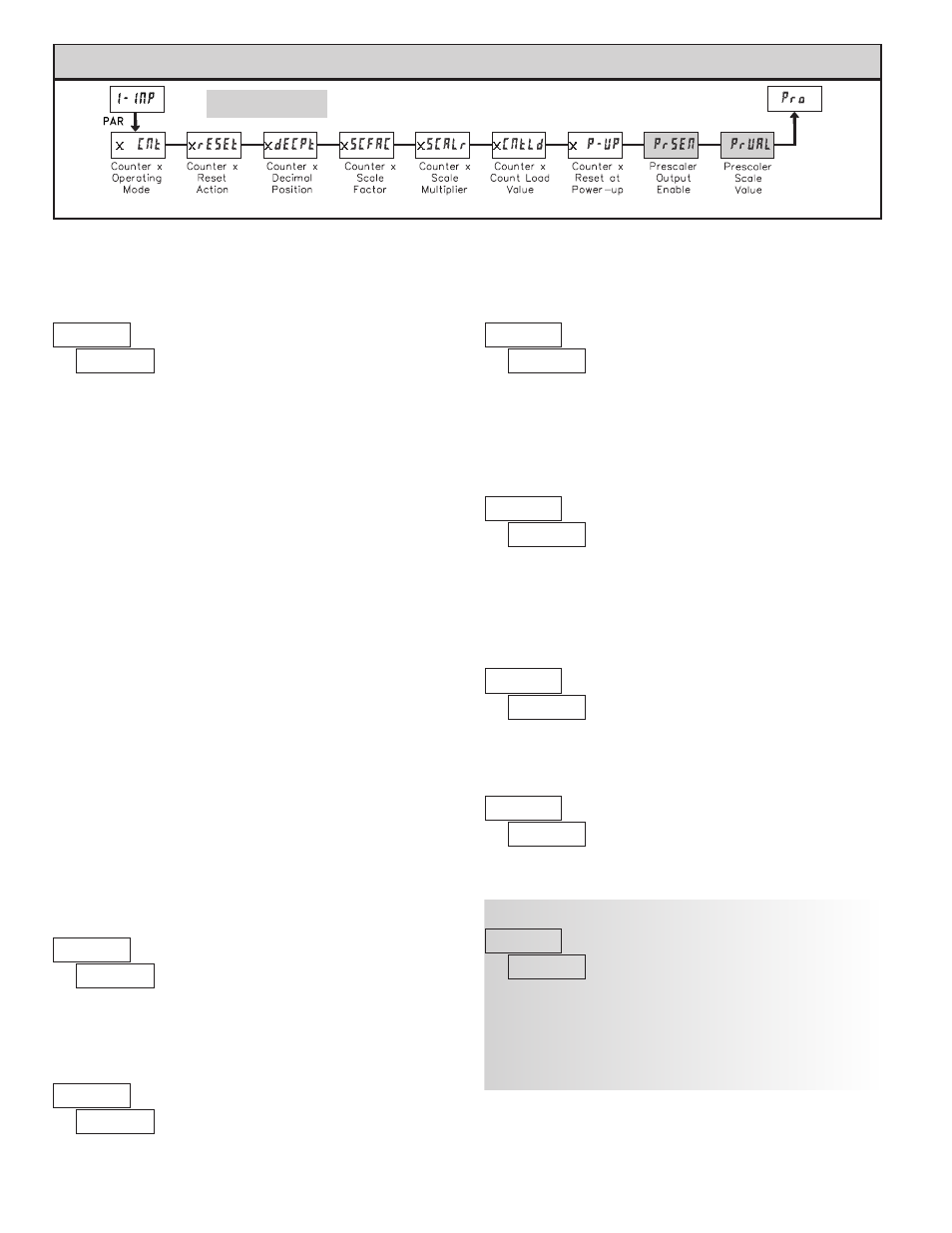
Module 1 is the programming for Counter A, Counter B and the Prescaler Output. Counter B parameters follow the Prescaler parameters. For
maximum input frequency, the counters should be set to mode NONE and the Prescaler to NO when they are not in use. When set to NONE
or NO, the remaining related parameters are not accessible. A corresponding annunciator indicates the counter being shown in the Display
Mode. An Exchange Parameter Lists feature for scale factors and count load values is explained in Module 2.
PARAMETER MENU
x = Counter A or Counter B
6.1 mOdule 1 - C
OunT
a & b i
npuT
p
arameTers
(
)
paXC & i