Troubleshooting – Red Lion PAXR User Manual
Page 29
PAXI: CALIBRATION
29
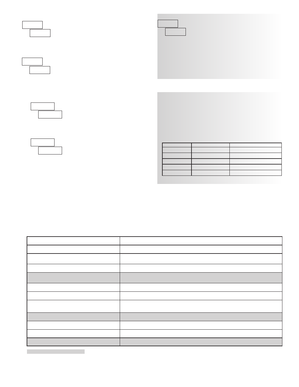
TROUBLESHOOTING
For further assistance, contact technical support at the appropriate company numbers listed.
PROBLEM
REMEDIES
NO DISPLAY
CHECK: Power level, power connections
PROGRAM LOCKED-OUT
CHECK: Active (lock-out) user input
ENTER: Security code requested
CERTAIN DISPLAYS ARE LOCKED OUT
CHECK: Module 3 programming
INCORRECT DISPLAY VALUE or NOT
COUNTING
CHECK: Input wiring, DIP switch setting, input programming, scale factor calculation,
input signal level, user input jumper, lower input signal frequency
USER INPUT NOT WORKING CORRECTLY
CHECK: User input wiring, user input jumper, user input being used for signal, Module 2
OUTPUT DOES NOT WORK
CHECK: Corresponding plug-in card installation, output configuration, output wiring
JITTERY DISPLAY
CHECK: Wiring is per EMC installation guidelines, input signal frequency, signal quality,
scaling, update time, DIP switch setting
“
”
RATE
CHECK: Lower input signal frequency, reduce rate scaling
MODULES or PARAMETERS NOT ACCESSIBLE CHECK: Corresponding plug-in card installation, related controlling parameter selected
ERROR CODE (
)
PRESS: Reset key (if unable to clear contact factory.)
SERIAL COMMUNICATIONS
CHECK: Wiring, connections, meter and host settings
Analog Output Card Calibration
Before starting, verify that a precision meter with an accuracy of 0.05% or
better (voltmeter for voltage output and/or current meter for current output) is
connected and ready. Then perform the following procedure:
1. Use the arrow keys to display
and press
PAR.
2.
is displayed. Use the arrow keys to select
and press
PAR.
3. Using the chart below, step through the five selections to be calibrated. At
each prompt, use the PAXI arrow keys to adjust the output so that the
external meter display matches the selection being calibrated. When the
external reading matches, or if the range is not being calibrated, press
PAR.
SELECTION
EXTERNAL METER
ACTION
00
0.00
Adjust if necessary, press
PAR
0
4.00
Adjust if necessary, press
PAR
00
20.00
Adjust if necessary, press
PAR
00
0.00
Adjust if necessary, press
PAR
00
10.00
Adjust if necessary, press
PAR
4. When
appears, press
PAR twice and remove the external meters.
The only item in the PAXI meter that can be calibrated
is the Analog Output. The Count A and B values are scaled
using the parameters in Module 1, Counter C value is scaled
using Module 5 and the Rate value is scaled using Module
4. If the meter appears to be indicating incorrectly or inaccurately, refer to the
Troubleshooting section.
When Analog Out recalibration is required (generally every 2 years), it
should be performed by qualified technicians using appropriate equipment.
Calibration does not change any user programmed parameters.
Calibration may be aborted by disconnecting power to the meter before
exiting Module 9. In this case, the existing calibration settings remain in effect.
Note: Allow a 30 minute warm-up period before staring calibration.
Shaded areas are model dependent.
INPUT A AND B LOGIC SELECTION
The Count Inputs A and B are factory configured for falling edge triggered
(active low) operation in single edge count modes. The Counter Operating Mode
descriptions in the Input programming section reflect this logic. If an application
is better suited to use rising edge triggered (active high) operation, the Input
Logic for Input A and/or Input B can be changed by entering Code 55.
Selecting
sets the Input A logic to rising edge triggered (active high)
operation. Be advised that all references to Input A falling edge and Input A
rising edge will be reversed for the Counter Operating Mode descriptions.
Selecting
sets the Input B logic to rising edge triggered (active high)
operation. Be advised that all references to Input B falling edge and Input B
rising edge will be reversed for the Counter Operating Mode descriptions.
The meter briefly displays the unit type followed by the
current firmware version (
x.x), and then returns to
. This information is also displayed during the
meter power-up sequence.
UNIT TYPE AND VERSION