6 module 6 - s, Etpoint, Larm – Red Lion PAXR User Manual
Page 20: Arameters, Spsel, Hys-n, Stb-n, Toff-n, Auto-n, Tout-n
20
20
6.6 mOdule 6 - s
eTpOinT
(a
larm
) p
arameTers
(
)
Setpoint
Annunciators
Output
Logic
Setpoint
Value
Power-up
State
Setpoint
Action
Setpoint
Assignment
Boundary
Type
Setpoint
Tracking
SPSEL
Setpoint
Select
PAR
6-SPt
Lit-n
SUP-n
ACt-n
ASN-n
SP-n
trC-n
tYP-n
Pro
OUt-n
tON-n
On Time
Delay
HYS-n
Setpoint
Hysteresis
Stb-n
Standby
Operation
PAR
tOFF-n
Off Time
Delay
Reset
w/SPn+1
Activates
AUtO-n
Counter
Auto Reset
tOUt-n
Time-out
Value
Reset
W/Display
Reset
rSd-n
rSAS-n
Reset
w/SPn+1
Deactivates
rSAE-n
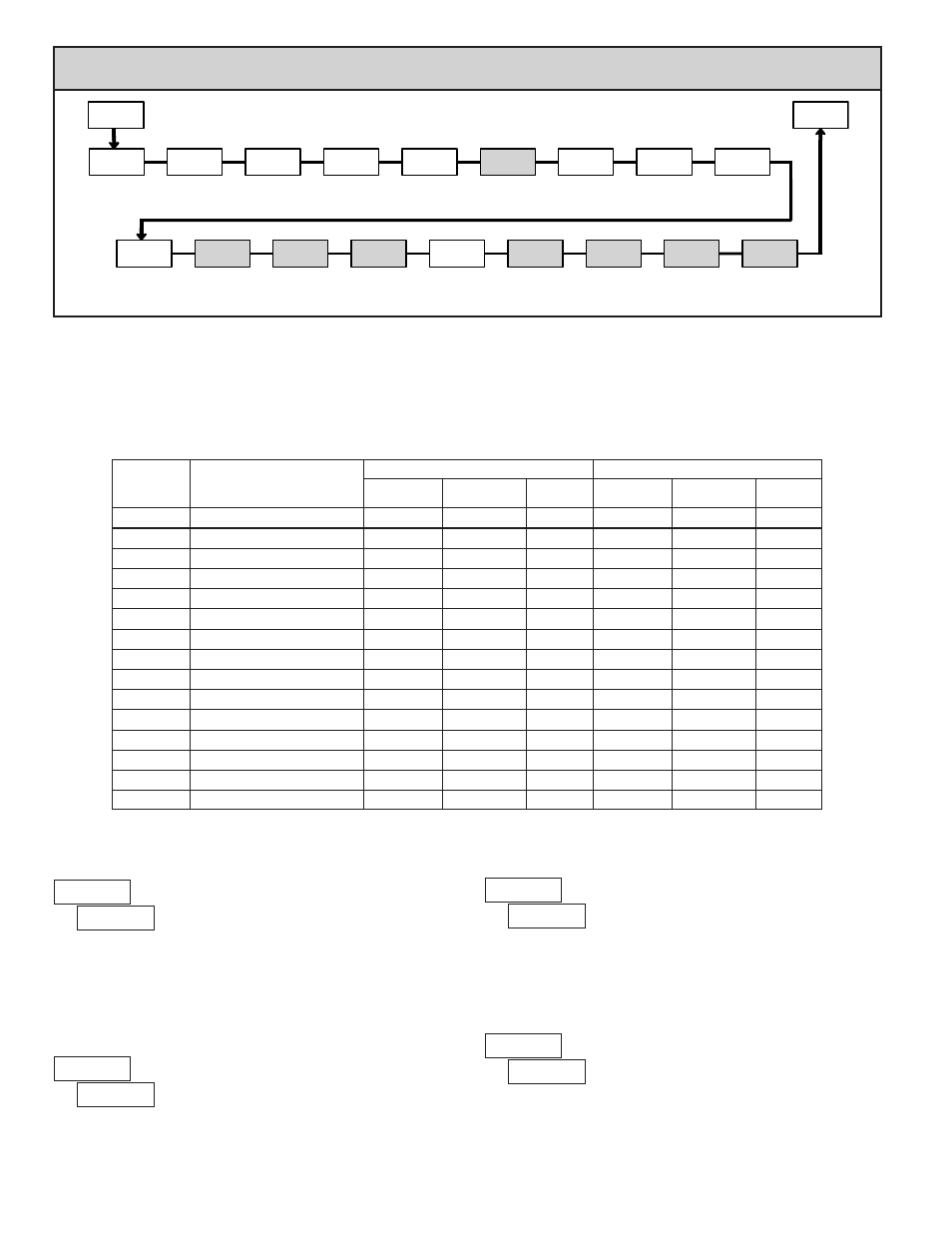
PARAMETER MENU
Module 6 is the programming for the setpoint (alarms) output parameters. To have setpoint outputs, a setpoint Plug-in card needs to
be installed into the PAX (see Ordering Information). Depending on the card installed, there will be two or four setpoint outputs
available. For setpoint hardware and wiring details, refer to the bulletin shipped with the plug-in card. For maximum input frequency,
unused Setpoints should be configured for
action.
The setpoint assignment and the setpoint action determine certain setpoint feature availability. The chart below illustrates this.
SETPOINT PARAMETER AVAILABILITY
SETPOINT SELECT
Select a setpoint (alarm output) to open the remaining module menu. (The
“
” in the following parameters will reflect the chosen setpoint number.) After
the chosen setpoint is programmed, the display will default to
. Select
the next setpoint to be programmed and continue the sequence for each setpoint.
Pressing
PAR at
will exit Module 6.
SETPOINT ANNUNCIATORS
disables the display of the setpoint annunciator. Normal (
) displays
the corresponding setpoint annunciator of an “on” alarm output. Reverse (
)
displays the corresponding setpoint annunciator of an “off” alarm output.
flashes the display and the corresponding setpoint annunciator of an
“on” alarm output.
SETPOINT OUTPUT LOGIC
Normal (
) turns the output “on” when activated and “off” when
deactivated. Reverse (
) turns the output “off” when activated and “on” when
deactivated.
SETPOINT POWER UP STATE
will restore the output to the same state it was at before the meter was
powered down.
will activate the output at power up.
will deactivate the
output at power up.
Yes
No
Yes
No
No
No
Reset When SPn+1 Deactivates
Yes
No
Yes
No
No
No
Reset When SPn+1 Activates
Yes
No
Yes
No
No
No
Reset With Display Reset
Yes
No
Yes
No
No
No
Counter Auto Reset
No
No
Yes
No
No
Yes
Setpoint Time Out
No
No
No
Yes
Yes
Yes
Setpoint On Delay
No
No
No
No
Yes
No
Setpoint Off Delay
No
No
No
No
Yes
No
Setpoint Hysteresis
No
Yes
No
Yes
Yes
Yes
Standby Operation
No
Yes
No
Yes
Yes
Yes
Boundary Type
Yes
Yes
Yes
Yes
Yes
Yes
Setpoint Tracking
Yes
Yes
Yes
Yes
Yes
Yes
Setpoint Value
Yes
Yes
Yes
Yes
Yes
Yes
Power Up State
Yes
Yes
Yes
Yes
Yes
Yes
Output Logic
Yes
Yes
Yes
Yes
Yes
Yes
Annunciators
LATCH
BOUNDARY
TIMED OUT
LATCH
BOUNDARY
TIMED OUT
COUNTER
RATE
DESCRIPTION
PARAMETER