Removing the covers, Figure 11, Installation – Outback Power Systems FLEXpower ONE One Fully Pre-Wired Single Inverter System Installation Manual User Manual
Page 26
Installation
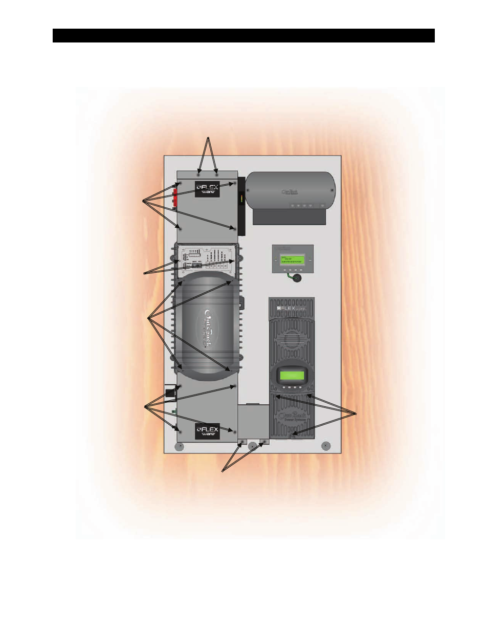
Removing the Covers
Remove the screws on
the Inverter Terminal
Access Cover (x2).
Remove the screws in
the AC Enclosure’s
Front Cover (x4).
Gently pull the Front
Cover away from the
chassis being careful
not to disconnect or
damage the wiring for
the Surge Protector.
The Front Cover cannot
be completely removed
due to the Surge
Protector wiring
(see page 52).
Remove the screws
on the Inverter DC
Cover (x4).
Remove the screws on
the DC Enclosure
Front Cover (x4).
1
Remove the screws on
the FLEXMax 80
Charge Controller
(x3).
1
Remove the screws on
the Raceway (x2).
1
The Raceway and front cover on the FLEXmax 80 Charge
Controller only need to be removed if the FLEXnet DC
Monitor is included in the configuration.
Remove the screws on the
AC Access Cover (x2).
Note: The AC Enclosure has two covers: the access cover
and the front cover. Both covers need to be opened to
make conductor connections. Once connections are
made, the access cover can be used for visual inspection,
so that the wiring will not be disturbed when inspected
by the local electrical authority.
Figure 11
Removing the Covers
24
900-0095-01-00 Rev A