1 . i – DAVIS Weather Monitor II (7440, 7440CS) User Manual
Page 5
System Components
Weather Monitor II
Page 1
1 . I
N T R O D U C T I O N
The Weather Monitor II provides sophisticated monitoring and logging of
essential weather conditions such as inside and outside temperature, baromet-
ric pressure, wind direction, wind speed and wind chill. This instruction man-
ual takes you step-by-step through the process of assembling, testing, and
installing your Weather Monitor II so you can begin collecting data as soon as
possible.
The standard station comes with all the sensors necessary to monitor the essen-
tial weather conditions described above. For instructions on how to install and
operate optional accessories, such as the Rain Collector or the External Temper-
ature/Humidity Sensor, please refer to the appropriate manual.
If you have a non-standard station (e.g. Wireless or EZ-Mount), please refer to
the separate installation manual provided before continuing with this installa-
tion.
S
YSTEM
C
OMPONENTS
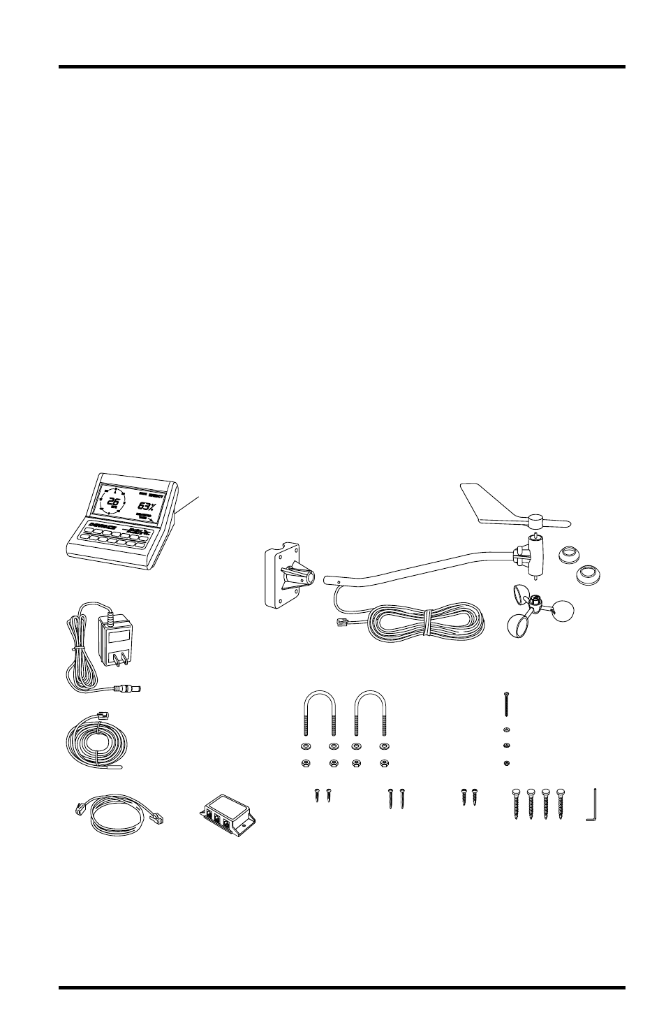
Your Weather Monitor II consists of the following components. Please check to
be sure you have all of the components listed before proceeding.
Anemometer
Base
Drip
Rings
Wind Cups
Wind Vane
Anemometer Arm
with 40 feet (12.2 meters)
of cable
AC-Power
Adapter
Weather Station Console
Mounting Base
attached to
bottom
of Console
Junction Box
Junction Box Cable
8 feet (2.4 meters) long
External Temperature Sensor
with 25 feet (7.6 meters)
of cable
U-Bolts
1/4"– 20 Hex Nuts
1/4" Flat Washers
4–40 x 1-1/8" Pan Head
Self-Threading Screw
#4 Flat Washer
#4 Lock Washer
4–40 Hex Nut
Allen
Wrench
1/4" x 1-1/2"
Lag Screws
#8 x 3/4"
Pan Head
Self-Threading
Screws
#6 x 1"
Pan Head
Self-Threading
Screws
#6 x 1/2"
Pan Head
Self-Threading
Screws
Cable Labels (not shown)