Canobd2&1 scan tool controls, Display functions – Equus 3140 - Scan Tool CanOBD2&1 Kit User Manual
Page 14
12
CanOBD2&1
E
CanOBD2&1 Scan Tool Controls
DISPLAY FUNCTIONS
DISPLAY FUNCTIONS
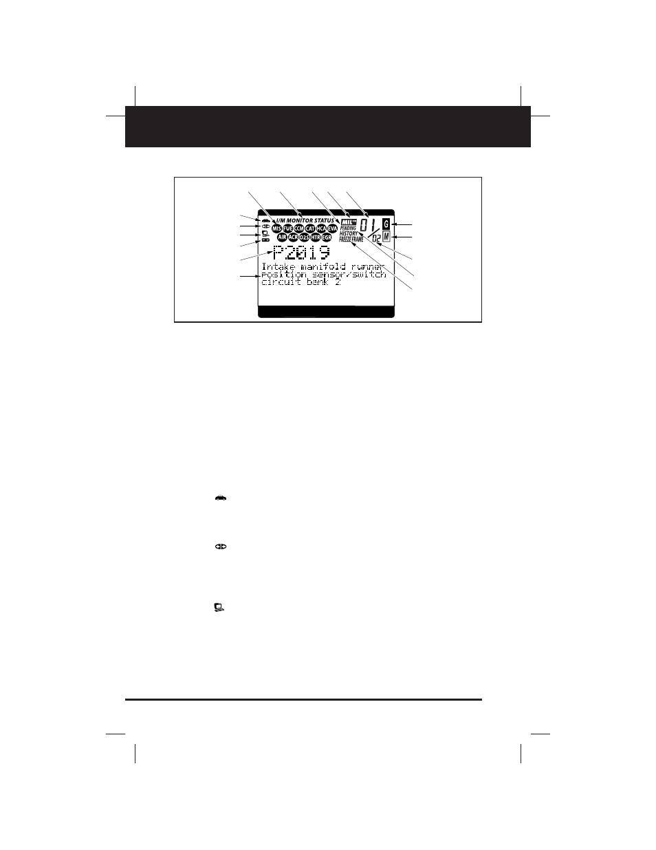
See Figure 2 for the locations of items 1 through 16, below.
1. I/M MONITOR STATUS field - Identifies the I/M Monitor status
area. (This function is applicable to OBD2 systems only.)
2. Monitor icons - Indicate which Monitors are supported by the vehi-
cle under test, and whether or not the associated Monitor has run
its diagnostic testing (Monitor status). When a Monitor icon is solid,
it indicates that the associated Monitor has completed its diagnos-
tic testing. When a Monitor icon is flashing, it indicates that the vehi-
cle supports the associated Monitor, but the Monitor has not yet run
its diagnostic testing. (This function is applicable to OBD2 systems
only.)
3.
Vehicle icon - Indicates whether or not the CanOBD2&1 Scan
Tool is being properly powered through the vehicle’s Data Link
Connector (DLC). A visible icon indicates that the CanOBD2&1
Scan Tool is being powered through the vehicle’s DLC connector.
4.
Link icon - Indicates whether or not the CanOBD2&1 Scan
Tool is communicating (linked) with the vehicle’s on-board comput-
er. When visible, the CanOBD2&1 Scan Tool is communicating with
the computer. If the Link icon is not visible, the CanOBD2&1 Scan
Tool is not communicating with the computer.
5.
Computer icon - When this icon is visible it indicates that the
CanOBD2&1 Scan Tool is linked to a personal computer. An option-
al “PC Link Kit” is available that makes it possible to upload
retrieved data to a personal computer.
4
3
2
1
11 12
13
5
8
9
10
14
16
15
6
7
Figure 2. Display Functions