HP StorageWorks 3000 RAID Array User Manual
Page 26
1-10 RAID Array 3000 Controller Shelf Hardware User’s Guide
Compaq Confidential – Need to Know Required
Writer: Bob Young Project: RAID Array 3000 Controller Shelf Hardware User’s Guide Comments:
Part Number: EK-SMCPQ-UG. D01 File Name: b-ch1 Product Overview.doc Last Saved On: 12/4/00 1:09 PM
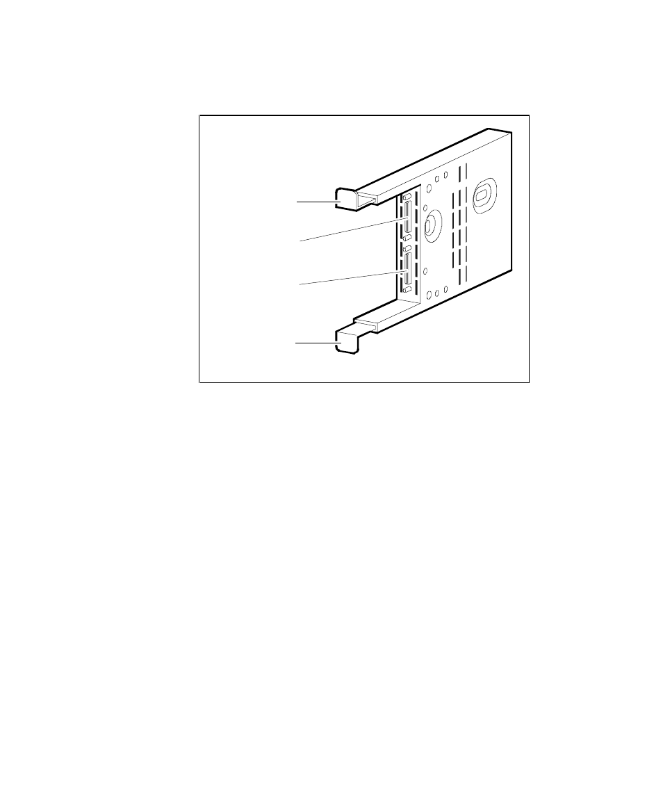
Figure 1-5 shows the Device I/O module.
SHR-1045
Upper
Mounting
Tab
Lower
Mounting
Tab
Device Port 0
Connector
Device Port 1
Connector
Figure 1-5. Device I/O module
The dual-channel device I/O module has two 68-pin VHDCI female
connectors mounted on the front panel (see Figure 1– 5). The upper connector
is the device port 0 connector. The lower connector is the device port 1
connector.
The device I/O module top and bottom guides properly align the module in the
shelf and with the backplane connector at the back of the shelf. When you
install the module the two spring mounting tabs expand and engage the shelf.
The combination of the mounting tabs and the backplane connector ensures
that the module is firmly seated.
The front edge of the internal circuit board in the device I/O module contains
two blower-status LEDs (see Figure 1– 6). Under normal operating conditions,
the LEDs are On. When there is a blower error or an over-temperature
condition, they Flash. The upper LED displays the status of the left blower and
the lower LED displays the status of the right blower. The blowers cool the
device I/O module by drawing air in through the slots in the front and
exhausting it out the rear of the shelf. Refer to the StorageWorks SBB Shelf I/O
Module User’s Guide supplied with the device expansion shelf for a
description of the blower status LEDs when troubleshooting a shelf-cooling
problem.