AMD Geode SC3200 User Manual
Page 76
76
AMD Geode™ SC3200 Processor Data Book
General Configuration Block
32581C
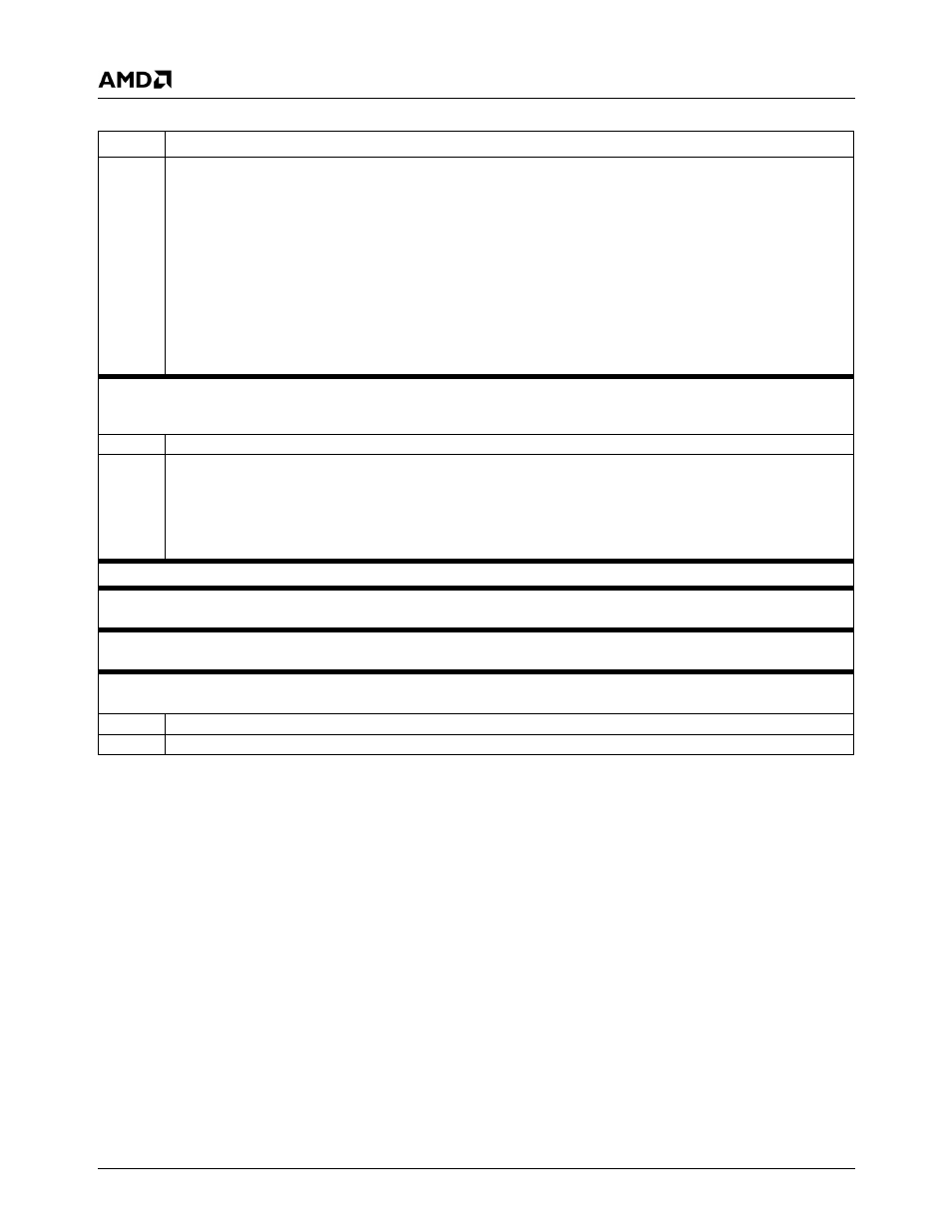
0
SDBE0 (Slave Disconnect Boundary Enable). Works in conjunction with the GX1 module’s PCI Control Function 2 Regis-
ter (Index 41h), bit 1 (SDBE1). Sets boundaries for when the GX1 module is a PCI slave.
SDBE[1:0]
00: Read and Write disconnect on boundaries set by bits [3:2] of the GX1 module’s PCI Control Function 2 register (Index
41h).
01: Write disconnects on boundaries set by bits [3:2] of the GX1 module’s PCI Control Function 2 register. Read discon-
nects on cache line boundary of 16 bytes.
1x: Read and Write disconnect on cache line boundary of 16 bytes.
This bit is reset to 1.
All PCI bus masters (including SC3200’s on-chip PCI bus masters, e.g., the USB Controller) must be disabled while modify-
ing this bit. When accessing this register while any PCI bus master is enabled, use read-modify-write to ensure these bit
contents are unchanged.
Offset 38h
Interrupt Selection Register - INTSEL (R/W)
Reset Value: 00h
This register selects the IRQ signal of the combined WATCHDOG and High-Resolution timer interrupt. This interrupt is shareable with
other interrupt sources.
7:4
Reserved. Write as read.
3:0
CBIRQ. Configuration Block Interrupt.
0000: Disable
0100: IRQ4
1000: IRQ8#
1100: IRQ12
0001: IRQ1
0101: IRQ5
1001: IRQ9
1101: Reserved
0010: Reserved
0110: IRQ6
1010: IRQ10
1110: IRQ14
0011: IRQ3
0111: IRQ7
1011: IRQ11
1111: IRQ15
Offset 39h-3Bh
Reserved - RSVD
Offset 3Ch
Device Identification Number Register - ID (RO)
Reset Value: xxh
This register identifies the device. SC3200 = 04h.
Offset 3Dh
Revision Register - REV (RO)
Reset Value: xxh
This register identifies the device revision. See the AMD Geode™ SC3200 Specification Update document for value.
Offset 3Eh-3Fh
Configuration Base Address Register - CBA (RO)
Reset Value: xxh
This register sets the base address of the Configuration block.
15:6
Configuration Base Address. These bits are the high bits of the Configuration Base Address.
5:0
Configuration Base Address. These bits are the low bits of the Configuration Base Address. These bits are set to 0.
Table 4-2. Multiplexing, Interrupt Selection, and Base Address Registers (Continued)
Bit
Description