AMD Geode SC3200 User Manual
Page 54
54
AMD Geode™ SC3200 Processor Data Book
32581C
FRAME#
D8
I/O
Frame Cycle. Frame is driven by the current master to
indicate the beginning and duration of an access.
FRAME# is asserted to indicate the beginning of a bus
transaction. While FRAME# is asserted, data transfers
continue. FRAME# is de-asserted when the transaction
is in the final data phase.
This signal is internally connected to a pull-up resistor.
---
IRDY#
F2
I/O
Initiator Ready. IRDY# is asserted to indicate that the
bus master is able to complete the current data phase of
the transaction. IRDY# is used in conjunction with
TRDY#. A data phase is completed on any PCI clock in
which both IRDY# and TRDY# are sampled as asserted.
During a write, IRDY# indicates that valid data is present
on AD[31:0]. During a read, it indicates that the master is
prepared to accept data. Wait cycles are inserted until
both IRDY# and TRDY# are asserted together.
This signal is internally connected to a pull-up resistor.
D14
TRDY#
F1
I/O
Target Ready. TRDY# is asserted to indicate that the tar-
get agent is able to complete the current data phase of
the transaction. TRDY# is used in conjunction with
IRDY#. A data phase is complete on any PCI clock in
which both TRDY# and IRDY# are sampled as asserted.
During a read, TRDY# indicates that valid data is present
on AD[31:0]. During a write, it indicates that the target is
prepared to accept data. Wait cycles are inserted until
both IRDY# and TRDY# are asserted together.
This signal is internally connected to a pull-up resistor.
D13
STOP#
G1
I/O
Target Stop. STOP# is asserted to indicate that the cur-
rent target is requesting that the master stop the current
transaction. This signal is used with DEVSEL# to indicate
retry, disconnect, or target abort. If STOP# is sampled
active by the master, FRAME# is de-asserted and the
cycle is stopped within three PCI clock cycles. As an
input, STOP# can be asserted in the following cases:
1)
If a PCI master tries to access memory that has
been locked by another master. This condition is
detected if FRAME# and LOCK# are asserted dur-
ing an address phase.
2)
If the PCI write buffers are full or if a previously buff-
ered cycle has not completed.
3)
On read cycles that cross cache line boundaries.
This is conditional based upon the programming of
GX1 module’s PCI Configuration Register, Index
41h[1].
This signal is internally connected to a pull-up resistor.
D15
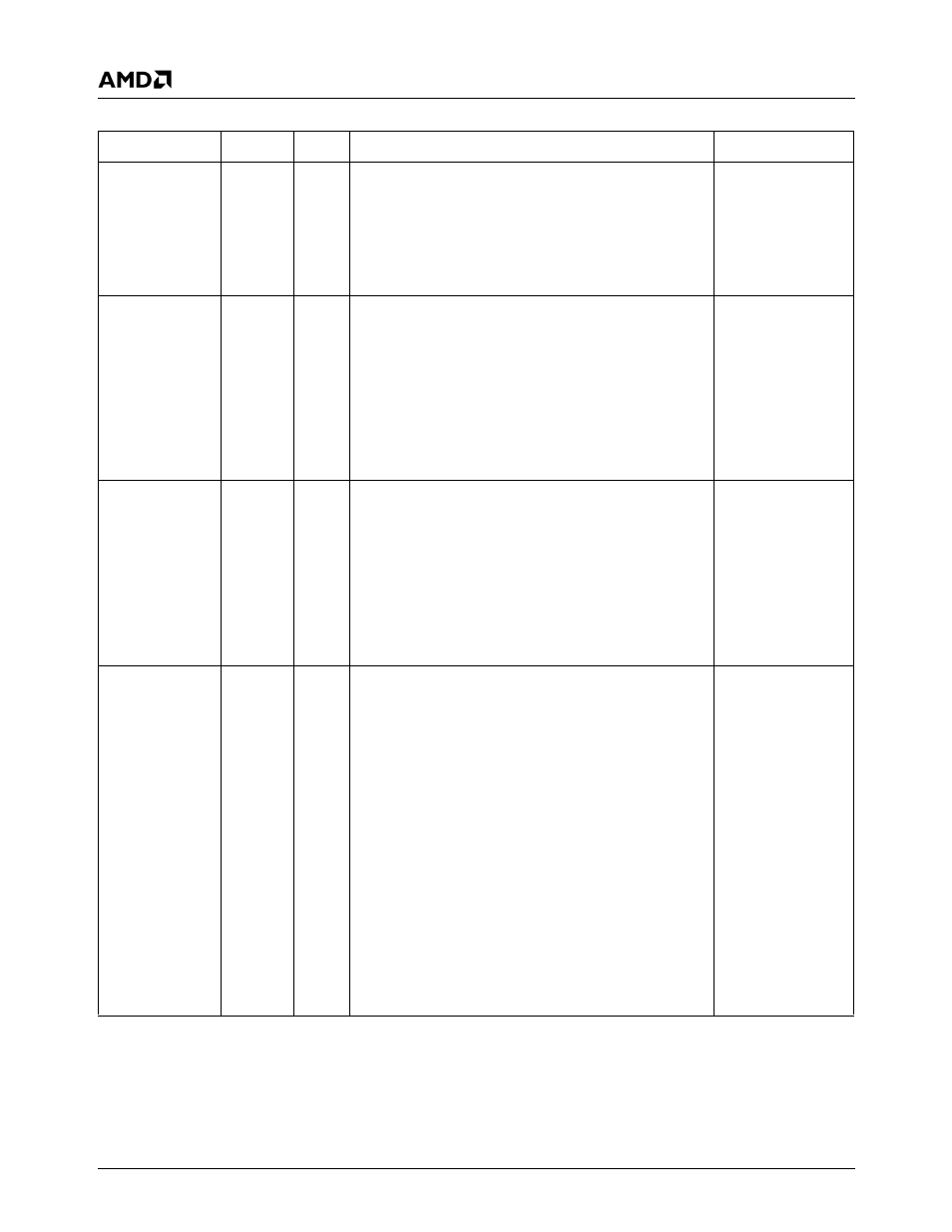
3.4.6
PCI Bus Interface Signals (Continued)
Signal Name
BalL No.
Type
Description
Mux