5 integrated pll, Figure 7-14, Pll block diagram – AMD Geode SC3200 User Manual
Page 326
326
AMD Geode™ SC3200 Processor Data Book
Video Processor Module
32581C
7.2.5
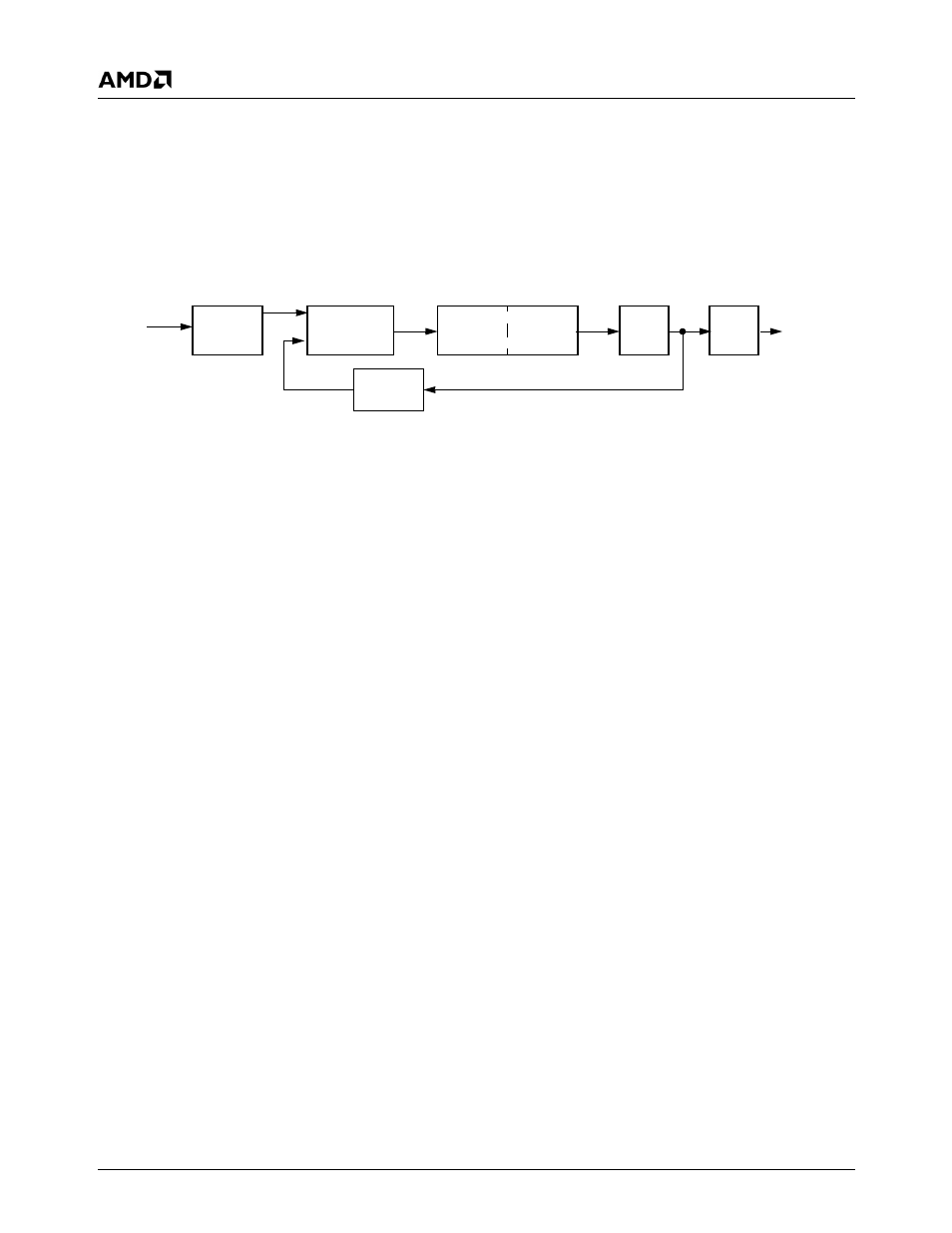
Integrated PLL
The integrated PLL can generate frequencies up to 135
MHz from a single 27 MHz source. The clock frequency is
programmable using two registers. Figure 7-14 shows the
block diagram of the Video Processor integrated PLL.
F
REF
is 27 MHz, generated by an external crystal and an
integrated oscillator. F
OUT
is calculated from:
F
OUT
= (m + 1) / (n+ 1) x F
REF
The integrated PLL can generate any frequency by writing
into the “m” and “n” bit fields (FBAR0+Memory Offset 2Ch,
m = bits [14:8] and n = bits [3:0]). Additionally, 16 prepro-
grammed VGA frequencies can be selected via the PLL
Clock Select register (F4BAR0+Memory Offset
2Ch[19:16]), if the crystal oscillator has a frequency of 27
MHz. This PLL can be powered down via the Miscella-
neous register (F4BAR0+Memory Offset 28h[12]).
Figure 7-14. PLL Block Diagram
F
REF
F
OUT
n
Phase
Charge
m
VCO
Compare
Divider
Divider
Pump
Loop
Filter
Out
Divide