Figure 9-27 – AMD Geode SC3200 User Manual
Page 390
390
AMD Geode™ SC3200 Processor Data Book
Electrical Specifications
32581C
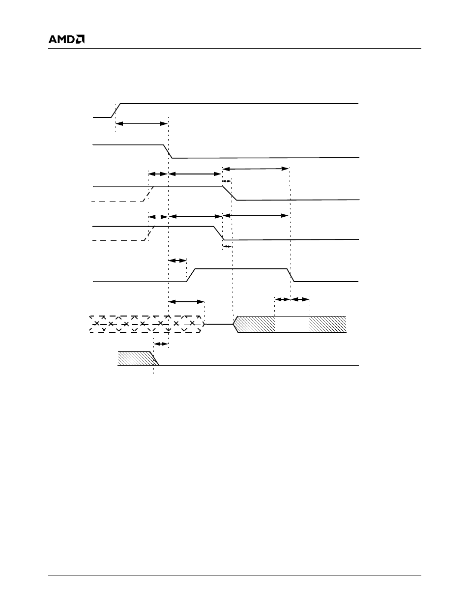
All timing parameters are measured at the connector of the
device to which the parameter applies. For example, the
sender stops generating STROBE edges t
RFS
after the
negation of DMARDY. Both STROBE and DMARDY timing
measurements are taken at the connector of the sender.
Figure 9-27. Initiating an UltraDMA Data in Burst Timing Diagram
t
UI
t
ACK
t
ENV
t
FS
t
FS
t
ZAD
t
ACK
t
ZIORDY
t
AZ
t
ACK
t
DVS
t
DVH
t
ENV
t
ZAD
IDE_DATA[15:0]
IDE_ADDR[2:0]
IDE_CS[0:1]
IDE_REQ0
(device)
IDE_DACK0#
(host)
IDE_IOW0#
(STOP0)
(host)
IDE_IOR0#
(HDMARDY0#)
(host)
IDE_IRDY0 (DSTROBE0)
(device)
Note:
The definitions for the IDE_IOW[0:1]# (STOP[0:1]), IDE_IOR[0:1]# (HDMARDY[0:1]#) and IDE_IRDY[0:1]
(DSTROBE[0:1]) signal lines are not in effect until IDE_REQ[0:1] and IDE_DACK[0:1]# are asserted.
- Radeon 4850 (18 pages)
- Phenom AM2r2 (6 pages)
- GA-K8N51GMF-9 (80 pages)
- Socket AM2+ Quad Core Processor SB750 (63 pages)
- Turion 64 X2 (2 pages)
- GA-M61PM-S2 (80 pages)
- Socket AM2+ Quad Core AMD Processor 790GX (53 pages)
- 7ZMMC (36 pages)
- Geode SC1200 (443 pages)
- CS5535 (36 pages)
- Geode LX800 (46 pages)
- ATI RADEON HD 2600 (62 pages)
- LE-363 (45 pages)
- SimNow Simulator 4.4.4 (269 pages)
- GA-MA69VM-S2 (88 pages)
- KM780V (21 pages)
- SBX-5363 (55 pages)
- AM79C971 (1 page)
- K3780E-S (43 pages)
- GEODE LE-366 (45 pages)
- 7ZX-1 (46 pages)
- Geode SC2200 (429 pages)
- Phenom II (6 pages)
- ATI Radeon x1700 FSC (22 pages)
- Turion 64 (3 pages)
- 1207 (62 pages)
- CrossFire 550X (16 pages)
- Athlon 27488 (104 pages)
- Geode LX [email protected] (680 pages)
- GA-M61SME-S2 (80 pages)
- N2PA-LITE (45 pages)
- GA-K8NSC-939 (80 pages)
- GEODE NX800LX (27 pages)
- Am79C930 (161 pages)
- LV-651 (50 pages)
- Athlon 6 (19 pages)
- SEMPRON 10 (102 pages)
- GA-K8N ULTRA-9 (80 pages)
- Geode LX CS5536 (8 pages)
- MINI-ITX LV-651 (50 pages)
- GA-K8N51GMF-RH (88 pages)
- ATI RADEON HD 2400 (64 pages)
- GA-M55S-S3 (88 pages)
- GA-M51GM-S2G (88 pages)