3 capture vbi mode, Figure 7-6 – AMD Geode SC3200 User Manual
Page 316
316
AMD Geode™ SC3200 Processor Data Book
Video Processor Module
32581C
3)
Field Interrupt.
When the field interrupt occurs on the completion of an
odd field, the interrupt must program the Video Data
Odd Base Address with the other buffer’s address. The
odd field will ping-pong between the two buffers. When
the interrupt is due to the completion of an even field,
the interrupt handler must program the GX1 module’s
video buffer start offset value (GX_BASE+Memory
Offset 8320h) with the address of the frame (both odd
and even fields) that was just received from the VIP
block. This new address will not take affect until the
start of a new frame. It must also program the Video
Data Even Base Address with the other buffer so that
the even field will ping-pong just like the odd field. The
field just received can be known by reading the Cur-
rent Field bit (F4BAR2+Memory Offset 08h[24]).
7.2.1.3
Capture VBI Mode
There are three types of VBI data defined by the CCIR-656
protocol: Task A data, Task B data, and Ancillary data. The
VIP block supports the capture for each data type. Gener-
ally Task A data is the data type captured. Just as in Cap-
ture Video mode, there are three registers that tell the bus
master where to put the raw VBI data in the GX1 module’s
frame buffer. Once the raw VBI data has been captured,
the data can be manipulated or decoded. The data can
also be used by an application. An example of this would
be an Internet address that is encoded on one or more of
the VBI lines, or have an application decode the Closed
Captioning information put in the graphics frame buffer.
The registers, F4BAR2+Memory Offset 40h, 44h, and 48h,
tell the bus master the destination addresses for the VBI
data in the GX1 module’s frame buffer. Five bits
(F4BAR2+Memory Offset 00h[21:17]) are used to tell the
bus master the data types to store. Capture VBI mode
needs to be enabled at F4BAR2+Memory Offset
04h[9,1:0]. The Field Interrupt bit (F4BAR2+Memory Offset
04h[16]) should be used by the software driver to know
when the captured VBI data has been completed for a field.
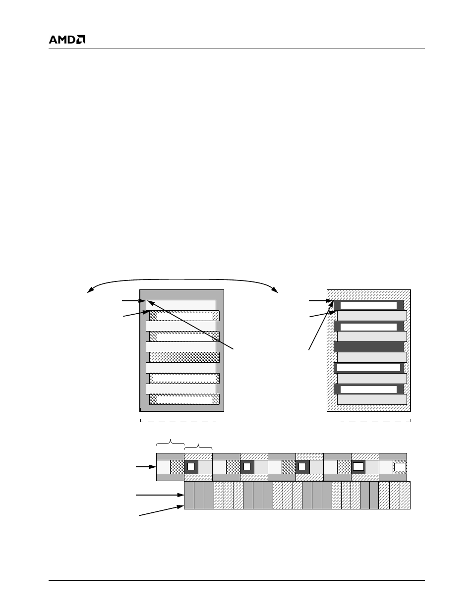
Figure 7-6. Capture Video Mode Weave Example Using Two Video Frame Buffers
Video Data Odd Base
F4BAR2+Memory Offset 20h
Video Data Even Base
F4BAR2+Memory Offset 20h
VID_START_OFFSET
GX_BASE+Memory Offset 8320h
Ping-pongs between the
two buffers during runtime
GX1 Module’s Video Frame Buffer
1
2
4
5
6
7
8
9
10
11
12
13
14
15
16
17
1
2
3
4
6
7
8
9 10 11 12 13 14 15 16 17 18 19 20
22
Capture video fill sequence
GX1 Module’s Display
5
5
21
Video Data Even Base
F4BAR2+Memory Offset 24h
Video Data Even Base
F4BAR2+Memory Offset 24h
Odd and Even fields are
Buf #2
Video Frame Buffer #1
Video Frame Buffer #2
18
23
5
11
3
7
Line 1 Odd Field
Line n Odd Field
Line 2 Odd Field
Line 1 Even Field
Line 2 Even Field
Line n-1 Odd Field
Line n-1 Even Field
Line n Odd Field
Line n Even Field
Line 1 Odd Field
Line 1 Even Field
Line 2 Odd Field
Line 2 Even Field
Line n-1 Odd Field
Line n-1 Even Field
Line n Even Field
15
18
85 frames per second
30 frames per second
Buf #1
Controller empty sequence
“Weaved” together
Ping-pongs between the two buffers during runtime