3 hygrogen2 assembly, E-m-hg2-s-v2.1 – ROTRONIC Hygrogen2 User Manual
Page 9
E-M-HG2-S-V2.1
Rotronic AG
Bassersdorf, Switzerland
Document code
Unit
HygroGen2: Humidity and Temperature Generator
with AutoCal/AutoCal+, Remote Control and
Range Extensions options.
Instruction Manual
Instruction Manual for Software
Version 2.1
Document Type
Page 5 of 75
Document title
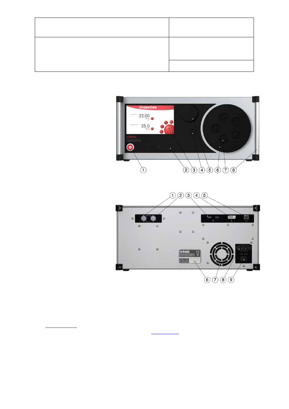
2.3 HygroGen2 Assembly
1)
Power switch
2)
USB ports
3)
Touch screen controller
4)
Water port
5)
Desiccant cell
6)
Chamber door
7)
Probe aperture bung
8)
Handle
1)
Sample loop return
2)
Sample loop outlet
3)
USB ports
4)
DVI monitor interface
5)
Ethernet socket
6)
Type label
7)
Fan outlet
8)
Electrical mains connection
9)
Power switch
HygroGen2 Chamber and Door
The HygroGen2 does not come supplied with a door. There are various standard and customized
versions available, depending on the intended use for the instrument, the use of an external reference
(see
) and the instruments under test. Figure 1(6) above shows the 15mm 5-port version
(part code: HG2-D-11111). Other options are listed in
To access the HygroGen2 chamber, remove the door. Grip firmly and twist the door anti-clockwise. In
the event that this proves difficult, cool the chamber first. Occasional application of silicone grease
around the door “O” ring seal will ease movement.
Figure 1: Front of HygroGen2
Figure 2: Rear of HygroGen2
© 2014; Rotronic AG
E-M-HG2-S-V2.1