ROTRONIC HygroLog TL-1D User Manual
ROTRONIC Tools
ROTRONIC AG, CH-8303 Bassersdorf
Tel. +41 44 838 11 44, www.rotronic.com
ROTRONIC Messgeräte GmbH, D-76275 Ettlingen
Tel. +49 7243 383 250, www.rotronic.de
ROTRONIC SARL, 56, F - 77183 Croissy Beaubourg
Tél. +33 1 60 95 07 10, www.rotronic.fr
ROTRONIC Italia srl, I- 20157 Milano
Tel. +39 2 39 00 71 90, www.rotronic.it
ROTRONIC Instruments (UK) Ltd, West Sussex RH10 9EE
Phone +44 1293 571000, www.rotronic.co.uk
ROTRONIC Instrument Corp, NY 11788, USA
Phone +1 631 427-3898, www.rotronic-usa.com
ROTRONIC Instruments Pte Ltd, Singapore 159836
Phone +65 6376 2107 www.rotronic.sg
ROTRONIC Shanghai Rep. Offi ce, Shanghai 200233, China
Phone +86 40 08162018, www.rotronic.cn
23
90
60
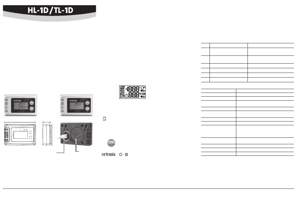
Type TL-1D
Type HL-1D
Data Loggers for Humidity and Temperature
SHORT INSTRUCTION MANUAL
General Description
Congratulations on your new ROTRONIC HL-1D (humidity and temperature) / TL-1D (tem-
perature) data logger. Please read these short instructions carefully before using the device.
These short instructions are limited to a description of the main functions and installation
of the device.
The HL-1D data logger can log up to 16,000 pairs of measured values (relative humidity and
temperature) in a range from 0 to 100 %RH and -20 to 70 °C.
The TL-1D data logger can log up to 32,000 temperature measured values in a range from
-20 to 70 °C.
Dimensions / Connections
Battery
compartment
(BAT.)
USB-Mini port
(settings and data download)
Inserting / Replacing the Battery
ROTRONIC HL-1D/TL-1D data loggers are powered by a CR2 battery.
To insert/replace the battery, open the BAT lid with a coin and insert the battery with the right
polarity (+/-). When closing the lid, make sure that the O-ring seal is positioned correctly.
Mechanical Installation / General Recommendations
Relative humidity is very temperature-dependent. The installation site can therefore have a
signifi cant infl uence on the performance of the device.
Follow the guidelines below to ensure optimum performance:
a) Select a representative installation site: install the device at a point where the humidity,
temperature and pressure conditions are representative of the environment that is to be
measured.
b) Ensure there is suffi cient air movement at the device: an air velocity of at least 1 meter
per second accelerates and facilitates adaptation of the probe to changing temperatures.
c) Avoid: (1) placing the device too close to heating elements, cooling coils, cold or hot walls,
in direct sunlight, etc. (2) placing the probe too close to steam injectors, humidifi ers,
in direct precipitation. (3) unstable pressure conditions with high air turbulence. (4)
accumulation of condensation at the contact wires of the sensor.
Mounting the Data Logger
The device can be placed at any point or mounted on a wall. Wall mounting: pull out the
two wall holders at the back of the device. Drill two holes and screw in screws. Then hang
the device on the screws.
COMM:
Appears when the device is connected to a computer
MIN/MAX/AVG: Press button briefl y to show MIN/MAX/AVG of the stored
measured values (only works in LOG mode)
FULL:
Appears when the memory is full
LOG:
Appears when the logging function is active
:
Appears when the battery is low
°C/°F, %RH:
Temperature and humidity unit
Hi, Lo:
Appears when the temperature or humidity is above the High Alarm
setting or below the Low Alarm setting
On/Off / Data Logging
Press button briefl y to switch the device on/off
(the device cannot be switched off when in logging mode).
To start or stop data logging, press the START/STOP button for a few seconds.
The right LED fl ashes green every fi ve seconds during data logging.
The left LED fl ashes red every fi ve seconds when values exceed/drop below the alarm settings
or when the battery is low.
Display
Settings / Viewing Recorded Data
A PC running the free ROTRONIC software HW4-lite (software code: included / HW4: download:
www.rotronic.com) is needed to make settings and download/view the recorded data. The
device and PC are connected to each other with a normal USB to USB-Mini cable (AC003).
The cover of the USB port on the device can be opened with a coin.
See the document E-M-HW4v3-F2-022_10 for a description of settings in the HW4 software.
Troubleshooting
Error
Problem
Solution
E02
Measured temperature value
is too low
Place the device in a normal environment
E03
Measured temperature value
is too high
Place the device in a normal environment
E31
Temperature sensor damaged
Send the device in for repair
E04
Temperature measurement error
Place the device in a normal environment
E11
RH calibration error
Repeat humidity calibration
E33
Circuit damaged
Send the device in for repair
Technical Data
Type of battery
1 x CR2
Battery life
3 years (at logging interval of 5 minutes)
Battery charge indicator
Yes (HW4 software and display / LED indicator)
Range of measurement /
application
0…100 %RH / -20...70 °C
Accuracy at 23 °C ±5 °C
±3.0 %RH / ±0.3 °C
Storage capacity
HL-1D: 16,000 data points (%RH + °C)
TL-1D: 32,000 data points (°C)
Logging interval
30 s to 24 h
Display
LCD, 2 lines, resolution of 1 decimal
LED indicator
2 LED’s
Right LED fl ashes green during data logging
Left LED fl ashes red when limits broken
or low battery
Housing protection grade
HL-1D: IP 67 (electronics)
TL-1D: IP67
Weight
85 g
FDA/GAMP compatibility
Conformity
Dimensions
90 x 60 x 23 mm