ROTRONIC HM4 User Manual
ROTRONIC Tools
12
.0
82
3.0
10
2
ROTRONIC AG, CH-8303 Bassersdorf
Tel. +41 44 838 11 44, www.rotronic.com
ROTRONIC Messgeräte GmbH, D-76275 Ettlingen
Tel. +49 7243 383 250, www.rotronic.de
ROTRONIC SARL, 56, F - 77183 Croissy Beaubourg
Tél. +33 1 60 95 07 10, www.rotronic.fr
ROTRONIC Italia srl
,
I- 20157 Milano
Tel. +39 2 39 00 71 90, www.rotronic.it
ROTRONIC Instruments (UK) Ltd, West Sussex, RH10 9EE
Phone +44 1293 571000, www.rotronic.co.uk
ROTRONIC Instrument Corp, NY 11788, USA
Phone +1 631 427-3898, www.rotronic-usa.com
ROTRONIC Instruments Pte. Ltd., Singapore 159836
Phone +65 6376 2107, www.rotronic.sg
ROTRONIC Shanghai Rep. Offi ce, Shanghai 200233, China
Phone +86 40 08162018, www.rotronic.cn
A
Congratulations on your new state-of-the-art HygroMet4. Please read these short instructions
carefully before installing the device.
These short instructions are limited to a description of the main functions and installation of the
device. The detailed instruction manual can be found on the internet at:
www.rotronic.com
HygroMet4 Tuchel
HygroMet4 Cable (with Tuchel)
Introduction
The meteorological probes in the HygroMet4 series are transmitters for relative humidity and
temperatute. The humidity is measured with heated sensors. Heating of the humidity sensor
enables the following properties / functions:
• elimination of thawing
• sensor cleaning
Mechanical Installation
General Recommendations
Relative humidity is temperature-dependent. In order to measure it exactly, the probes and
sensors must be set exactly on the temperature level of the environment that is to be measured.
The installation site can therefore have a signifi cant infl uence on the performance of the device.
Follow the guidelines below to ensure optimum performance:
a) Select a representative installation site: Install the probe at a point where the humidity,
temperature and pressure conditions are representative for the environment that is to be
measured.
b) Ensure there is suffi cient air movement at the probe: An air velocity of at least 1 meter per
second accelerates and facilitates adaptation of the probe to changing temperatures.
SHORT INSTRUCTION MANUAL
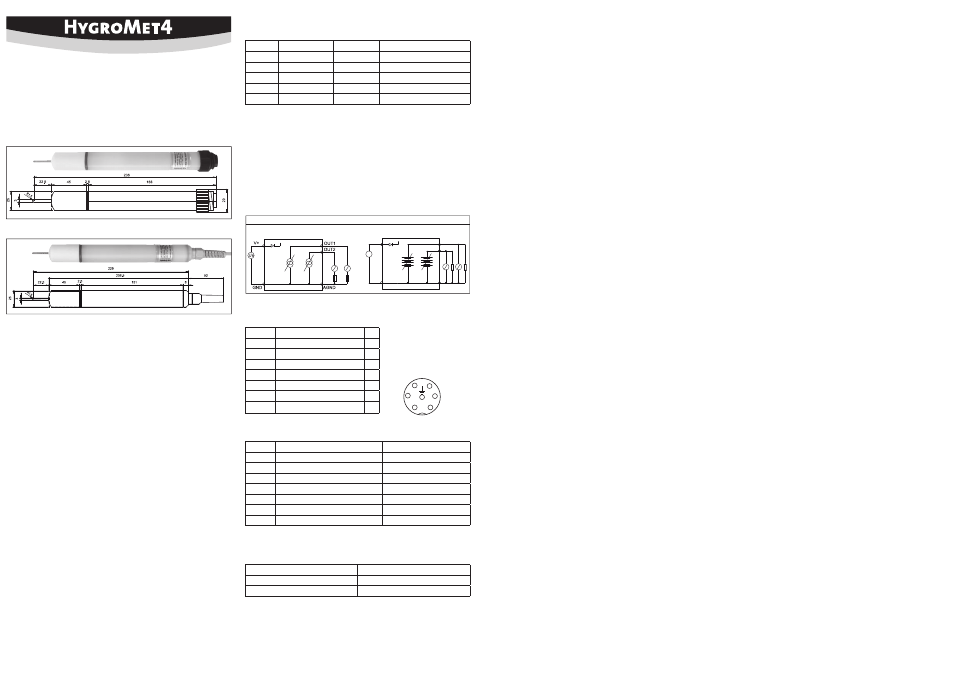
Pin Confi guration / Wiring Diagram
Analog Outputs and GND
To prevent measurement errors, analog ground AGND must also be used for the
analog outputs.
A
Current Output
Diagram
V+
GND
OUT2
OUT1
AGND
U
B
Voltage Output
HygroMet4 Tuchel
At housing or remote with cable
Description
PIN
V +
Power supply +
1
GND
Power supply GND
2
AGND
Analog signals GND
3
OUT2
Analog output 2:
Temperature
4
RS-485 +
RS-485 +
5
OUT1
Analog output 1:
Humidity
6
RS-485 −
RS-485 −
R
HygroMet4 Cable
Description
Wire Color
V +
Power supply +
Green
GND
Power supply GND
Gray / Shield
AGND
Analog signals GND
Yellow
OUT2
Analog output 2:
Temperature
Brown
RS-485 +
RS-485 +
Red
OUT1
Analog output 1:
Humidity
White
RS-485 −
RS-485 −
Blue
Service Cable
Depending on the version of HygroMet4 different cables need to be used:
For HygroMet4
Service Cable
With cable and open ends
AC3010
Tuchel connector direct or extended with cable AC3010-T
Solder Side
2
3
4
5
6
1
Scaling / Adjustment / Firmware Update
The following settings can be made using the HW4 software and correct service cable:
• new scaling of the outputs
• fi rmware update
• adjustment of the probe
• setting of the heater and sensor cleaning
Programming
The basic settings of the devices are made in the factory according to your order. The transmitters
are adjusted in the factory and therefore do not need to be checked and readjusted during instal-
lation. The devices can be started immediately after installation.
Periodic Calibration of the Probe
Both the temperature sensor and the corresponding electronics are very stable and do not normally
need to be changed or calibrated after factory calibration.
The long-term stability of the ROTRONIC SMD thermo sensor is typically better than 1 %RH per year.
For maximum accuracy we recommend calibration of the probe about every six to 12 months. More
frequent calibration can be necessary in applications where the sensor is exposed to pollutants.
The calibration can be performed by the user himself on site or in the laboratory / workshop. For
routine calibrations the probe should be checked at one or two points.
For all further details on calibration, please see the full version of the instruction manual, which
you can download from the internet.
Filter Cleaning
The fi lter can become soiled by dust in the air and must be replaced periodically.
Technical Data (Operation)
Humidity:
0...100 %RH
Temperature
– 40...85 °C
Accuracy humidity
heated: 1.5 %RH
Accuracy temperature
0.1 °C
Supply voltage
(5) 15...24 VDC depending on type
Rated current consumption
With sensor heating
<55 mA at V+ = 5 VDC
<30 mA at V+ = 24 VDC
Without sensor heating
<35 mA at V+ = 5 VDC
<20 mA at V+ = 24 VDC
Protection:
IP65
Accessories & Spare Parts
Art. No.:
Description
AC3010
Service cable for connection of cables with open ends
AC3010-T
Service cable for connection of a Tuchel connector
NSP-25-PE
Polyethylene (replacement) fi lter
EM-25-HM
Calibration device for Ø 25 mm HygroMet probes
EAXX-SCS
Humidity standard XX = 00,05,10,11,20,34,50,60,65,75,80,95 %RH
Electrical Installation
Power Supply
Type
Analog Outputs
Digital
Power Supply
HM431
0...20 mA
RS-485
15...24 VDC
HM432
4...20 mA
RS-485
15...24 VDC
HM433
0...1 VDC
RS-485
5...24 VDC
HM434
0...5 VDC
RS-485
15...24 VDC
HM435
0...10 VDC
RS-485
15...24 VDC
Caution: Wrong supply voltages and excessively high loading of the outputs can
damage the transmitter.