A2: temperature control, Appendix a2, E-m-hg2-s-v2.1 – ROTRONIC Hygrogen2 User Manual
Page 63
E-M-HG2-S-V2.1
Rotronic AG
Bassersdorf, Switzerland
Document code
Unit
HygroGen2 Humidity and Temperature Generator:
Instruction Manual
Appendix
Instruction Manual for Software
Version 2.1
Document Type
Page 59 of 75
Document title
Caution:
When tightening or releasing the Swagelok connectors do not apply torque to the nut/caps
without using a spanner on the connector body to counteract it. Finger tighten and then
apply a quarter turn with a spanner.
Replace the blanking caps when not using the sample loop.
If the chilled mirror instrument is being used in conjunction with a thermometer (in order to calculate
relative humidity), the temperature probe should be positioned in the chamber. Care should be taken
to ensure that insertion depth and stem conduction effects do not induce measurement errors.
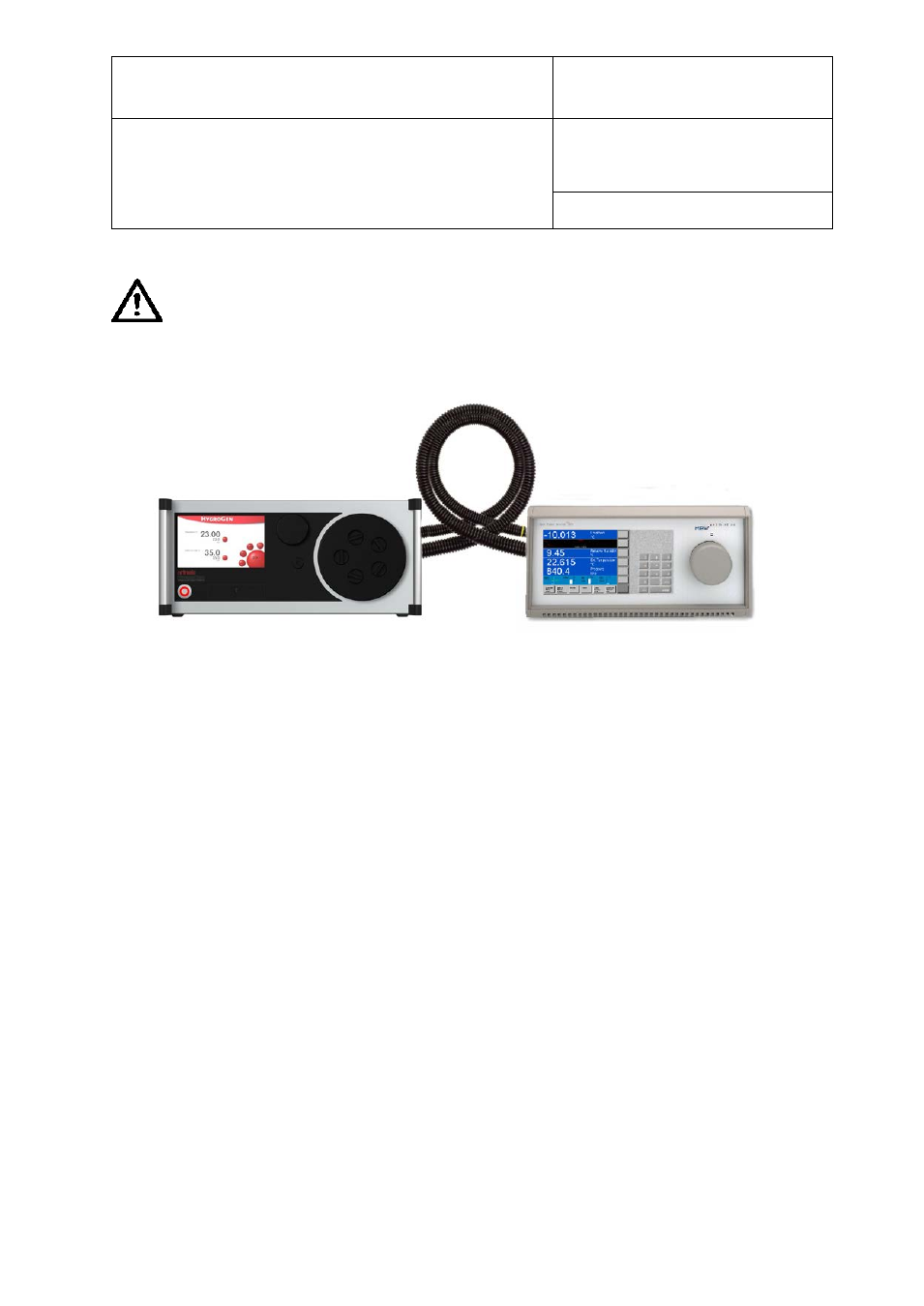
A typical HygroGen2/Chilled Mirror set up is shown at Figure 38; note the heated sample lines to the
rear.
Set the flow rate through the sample loop according the mirror instrument manufacturer’s
specifications. A lower flow rate will improve stability criteria but may influence measurement
response time.
A2: Temperature Control
Temperature control within the HygroGen2 is performed by a fast response PT100 thermometer
which is continuously referenced against the HygroClip control probe. The chamber is not considered
stable (as indicated by the control indicator being coloured green) unless the reported temperature
values are within the resolution of the control HygroClip.
If a replacement HygroClip reference is put into the HygroGen2, and it gives a significantly different
temperature reading, it may take a while - roughly 20 minutes for every 0.1°C discrepancy - the first
time stability control is engaged, as the self-adjustment algorithm runs.
Figure 38: HygroGen2/Chilled Mirror Set
© 2014; Rotronic AG
E-M-HG2-S-V2.1